

What is Noise?
Noise in signal measurement is unavoidable. It obscures interesting and useful signals, and might occur due to either properties of your circuitry, or even simply the test system you are using to measure. In this post, we want to find out what exactly this noise is, where it comes from, and how to address it through the proper design of our test system.
So, what is it? It’s essentially any variation in the voltage of a measured signal that obscures the theoretical true wave you are trying to achieve. Noise is caused by charge carrier fluctuations in different materials or at the junction boundary between two different materials used to build electronic components and PCBs. Due to non-deterministic movement of carriers, noise is a random phenomenon that cannot be described by periodic/harmonic amplitude, frequency and phase. Therefore, we typically characterize noise based on its energy distribution across the frequency range of interest. Power spectral density (PSD) is the function that defines the probability of noise energy to be distributed across the frequency spectrum. This function resembles a Bode plot, but without the phase information.
Depending on the PSD shape, the noise energy can be frequency dependent or frequency independent. Frequency independent noise has its energy evenly distributed across the entire frequency spectrum and this is what we call white noise. Frequency dependent noise may have its energy concentrated to low frequencies or to higher frequencies. We typically associate colors to frequency dependent noise, such as pink for 1/f noise.
In signal acquisition and processing systems is most often useful to calculate the ratio between the wanted signal energy and the total noise energy integrated across the noise bandwidth. The resulting parameter is the Signal-to-Noise Ratio (SNR) that essentially defines the minimum signal amplitude/power that we can still distinguish from random noise.
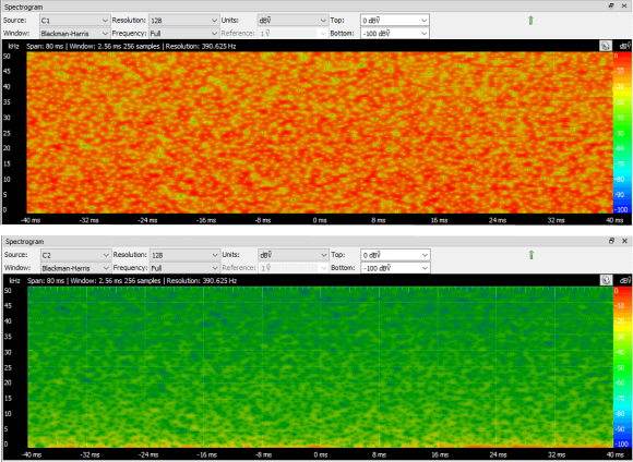
Resistive circuits generate only white noise whose energy is proportional to the resistance. Beside white noise, active circuits also generate 1/f and shot noise whose energy is much higher in a few hundreds of Hz or kHz range and slowly fades into a white noise as frequency increases. So the typical PSD of a circuit will have a low pass shape that settles to the white noise floor. This easily visible if you look at the spectrum of a scope channel with the input terminated to GND.
Resolution on your measurement instrument can also affect the impact of noise. A higher resolution means that you can measure smaller signals – which are more impacted by noise. More bits means less voltage per bit. High resolution also means that you can “spend” some of the extra bits on software filtering, with a similar effect from having a high bandwidth.
While noise can be an unwelcomed guest, it isn’t always the worst thing that can happen to your measurements. High amplitude or low frequency signals are less susceptible to many of the sources of noise that you can adjust for. Conversely, the more precise signals you are measuring, the likelier you are to have an issue with noise being present. Think of it like this – when you zoom in a photo lens for a picture, you’re far more apt to notice that bread crumb on the lens than in a wide shot.
How to Reduce Noise in Measurements
Unfortunately we cannot completely get rid of the noise, but we can use different design techniques to reduce the noise energy:
- Environmental Noise – We can use proper probing techniques that minimize antenna loops formed between the probe tip and GND. This is why for certain measurements we use pigtail type GND leads rather than actual wires.
- Circuit Noise – The acquisition circuit’s own noise can be reduced by the choice of resistive elements and by placing any gain stage as early as possible in the signal chain. This prevents amplifying the cummulated noise late in the chain.
- Quantization Noise – Quantization noise, inherent to all systems that contain an ADC, is a special type of noise introduced by the truncation of an analog value to a certain number of bits used to represent signal samples. It can be reduced by higher resolution ADCs and by low leakage at the sampling capacitor.
- Hardware Bandwidth Filter – Hardware low-pass filters attenuate high frequency content of both wanted signals and noise signals and can reduce out-of-band noise energy. Hardware filters are analog components and are not affected by quantization noise compared to their digital counterparts. The usage of these filters is dependent on what we are looking for in the tested circuit, the same way as probe bandwidth matters in probing. Another important aspect of low pass filtering before quantization is that they filter out high frequency spectral content that can be aliased back on top of the wanted signal.
- Use Probes with the Correct Impedance – Passive probe impedance is correlated with probe bandwidth. Probes on 1:1 setting are transparent in terms of impedance and only add a small contribution the the scope channel input impedance, typically (1M || 10-20pF). With 10:1 setting, the probe introduces a 9M resistor into the signal path to form a 1:10 voltage divider with the scope channel input impedance. The capacitance is now reduced and bandwidth is also much higher on the 10x setting compared to 1x. Therefore, the probe contributes to the noise by both adding its own noise and by passing the external noise energy across a larger frequency range. We should probe signals with the minimum bandwidth and division ratio required to see the desired effect. Another impedance-related measure is to break the GND loop, meaning to avoid different voltages at different GND point caused by lead impedance and return currents.
- Software Filtering – Oversampling, decimation and averaging done in software can exploit the random nature of the noise. For example, acquiring multiple frames of the same data and calculating the average for each sample between frames will tend to eliminate random spikes and will retain only deterministic values that occur identically between frames. Oversampling, in Digilent’s own instruments, means to acquire several frames with the same trigger point but with different phases of the sample clock. This procedure allows us to have additional data points between consecutive edges of the sample clock. This spreads the in-band quantization noise energy to a wider frequency range, thereby allowing a lower in-band noise amplitude and higher SNR. Decimation only retains every Nth sample and is almost always used together with a digital anti-aliasing filter that reduces noise bandwidth. Some ADC-s (e.g. sigma-delta) use noise shaping to move noise energy outside the wanted signal frequency range.
Kalite kontrol amorti yok işlerde.