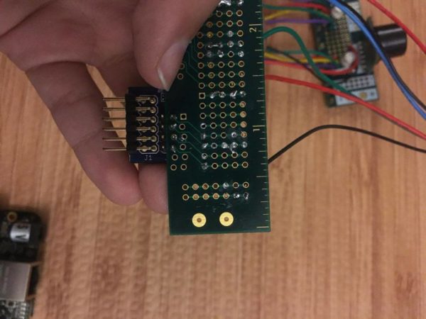
Recently Ella has been working on a project around the office that looks pretty cool. She has made it so one of the PCB Rulers lights up an LED when held level!
This simple but useful tool is just one of the many capabilities of the PCB Ruler.

Below is the list of materials she used for this project:
Hardware:
- PCB Ruler
- BeagleBone Black
- PmodGYRO
- LED (of any color)
- Soldering Iron
- (2) 4.7 kohm resistors
- Software:
- LabVIEW 2014
- LINX 3.0
I inquired with her about how it was all going to work, and she explained:
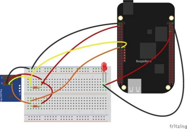
“The PmodGYRO runs using I2C communication protocol. All you need is one column on the J2 pin out on the PmodGYRO – VCC, GND, SDA and SCL. The Pmod is powered with 3.3V, and I use two, 4.7Kohm pull-up resistors to pull the SDA and SCL lines to 3.3V.”
For the build itself, she started by assembling the hardware then moved on to the software using LabVIEW and LINX. You can see her circuit diagram below, and check out her Instructable for detailed instructions and to download the LabVIEW code!

Stay tuned for the update where she expands upon the project… with sonar capabilities!

