

This Instructable by design a multiplexer, a decoder, an encoder, and a shifter using Verilog HDL. “Instead of building the circuit using logic operators, you will learn to describe a circuit behaviorally according to the functionality you wish the circuit to perform,” says Nate.
You’ll need to have the Vivado WebPACK installed on your computer and to have your FPGA set up. Knowing combinational logic in Verilog is a plus, too.
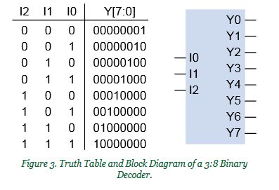
Background information on what each item is isn’t included, but there are some handy links in the project. First, details for the multiplexer, or mux, are listed. Then, you have to design one! Code it, and then move on to the binary decoder and priority encoder. The shifter is the final item to complete. At that point, you can test your knowledge by creating modified variations!
More information and code is available in the Instructable. Check it out and let us know what you think!