

We have less than a week for our OpenScope Kickstarter and we thought it would be a great to spend time with our lead design engineer, Keith Vogel on how he designed OpenScope and to answer the question: How good is good?
Larissa: Keith, you started working on OpenScope about two years ago. One of the really remarkable things about this product is how much is actually using the resources of the MCU. What kind of results can you actually get using just the analog circuitry on a micro controller?
Keith: The initial design requirement for the OpenScope was to be WiFi enabled 1MHz scope. But then we had to ask ourselves what makes a 1MHz scope useful, and what other features are needed. Using the experience of our Analog Discovery we concluded that we also needed a function generator, some sort of DC power supplies and a logic analyzer. This was challenging task considering we were going to implement this on a 200MHz PIC32MZ. To achieve this, most of the instrumentation firmware had to be offloaded on to the PIC32MZ’s peripherals so that the CPU could be freed up to service the WiFi/Network Stack and other housekeeping tasks. The PIC32MZ has 5 dedicated 3.125MS/s ADC, 1 shared ADC, 8 DMAs, 6 UARTs, 6 SPIs, 9 PWMs, 9 timers, and more. The idea was to set up these peripherals, get them running and let them go without CPU intervention.
Larissa: Wow. So pretty much every single resource that is available to the PICMZ. Do you have an example?
Keith: Yes, for example, the function generator; we put a pattern in memory, point the DMA at the memory, set up a timer to trigger the DMA at 10MS/s, and just let the DMA push the data buffer out to the IO port at a very regular 10MS/s; once it is set up, no CPU needed. The R2R ladder on the board acts as a DAC converting the 10bits of data toan analog signal. A low pass filter smooths the waveform. We get great results at 100KHz, and good results up to 1 MHz with only a -2db attenuation at 1 MHz.
Larissa: So really good?
Keith: Yeah, let’s look at some screen shots taken from my bench top scope.
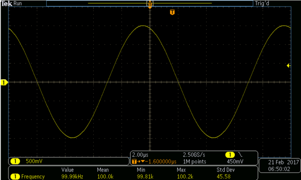
If I set up the OpenScope to generate a 3V, peak to peak waveform at 100KHz the below graph is what I get:
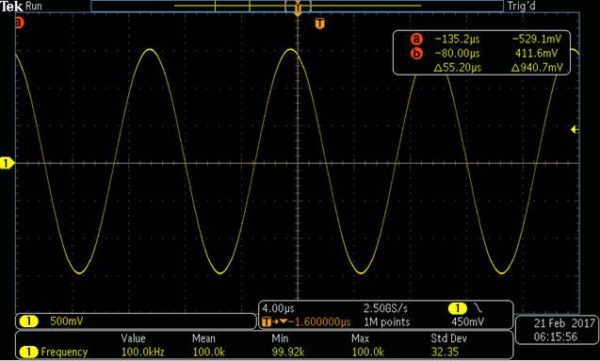
Then, if I make the timing tighter (from 4uS to 4nS, then we get a graph that is pretty much the same).
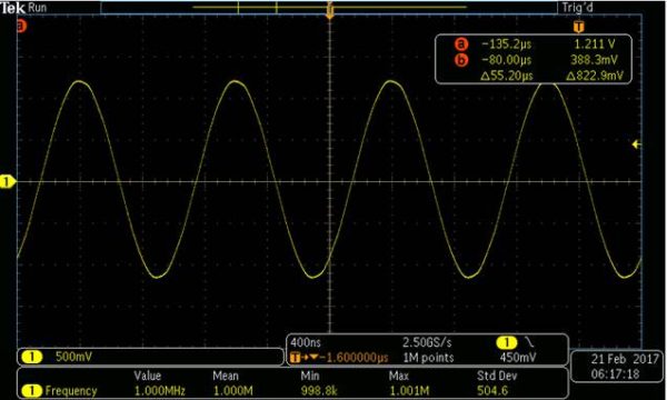
This is a 3V Peak to Peak 1 MHz waveform generated by the OpenScope… -2db attenuation. There are only 10 samples in each period creating the waveform!
Larissa: I think it’s amazing that you got such a low noise waveform generator like this running in the PICMZ just using the peripherals and an R2R ladder (no DAC). Did you have to do something special to the onboard ADCs to be able to get that kind of sample rate with such low loss of signal? Is the Oscilloscope similar?
Keith: Yes, the sampling of the ADC work in a similar fashion. A timer is set up to trigger the ADCs, the ADC completion event is setup to trigger a DMA transfer to memory. Once set up, the ADC just sample and the DMA transfer the samples into a buffer with no CPU utilization. The PIC32MZ ADCs only sample at 3.125MS/s and we thought that only having 3+ samples for a 1MHz scope was probably too few, so we interleaved 2 ADCs to double the sample rate. The OpenScope has 2 analog scope channels so we used 4 of the 5 dedicated ADCs to get 2 6.25MS/s ADCs.
Larissa: That’s a lot of data that is being transferred from the on-board ADCs. In most microcontroller designs, I would think the entire microcontroller would be used up trying to handle that data, but it sounds like you got around that by using the DMA (Direct Memory Access). Is that right?
Keith: Yes, basically everything runs in the microcontroller’s peripheral set and barely touches the CPU. This lets the CPU to be free to run the WiFi/Network stack, SD card, command parsing, LEDs, and other tasks. This also allows all of the instruments (like the logic analyzer, waveform generator, etc) to run concurrently.
Larissa: Okay, that’s impressive, the microcontroller sounds completely utilized. Is there a way that you could test it?
Keith: Yes, one very interesting test is loop back test where the output of the Waveform Generator loops back into the Oscilloscope inputs and sampled. This utilizes a lot of the OpenScope resources, 2 PWMs, 2 ADCs, 3 DMAs, 4 Timers; while running an SPI for the WiFi, another SPI for the SD card, a UART for COM port communications (which uses another 2 DMAs + the UART) and since the DC outputs are always running, another 2 PWMs for them. Summing this all up for this simple test we are running…
1. 5 DMAs
2. 4 Timers
3. 4 PWMs
4. 2 ADCs
5. 2 SPIs
6. 1 UART
7. CPU is running the WiFi/Network stack, HTTP server, LEDs, and instrument communications.
What would be interesting to know now is… exactly how good are the circuits? The simple loopback test should sample what we think we are generating, and will run through a ton of the OpenScopes hardware and software. So let compare our 100kHz sampled waveform to what we are generating.
On the Tek scope, I get this graph:
When we compare this output to the Oscilloscope in Waveforms Live using the OpenScope, we see this graph!
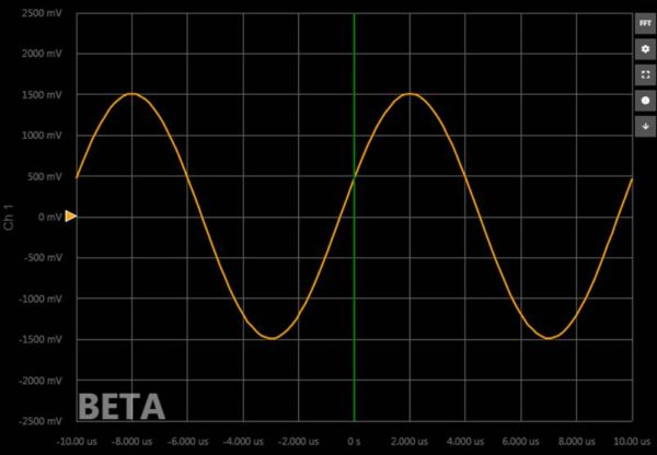
This is what we actually sample! It is very comforting to see that they look the same Not only is our wavegen good, but our sampling is too!
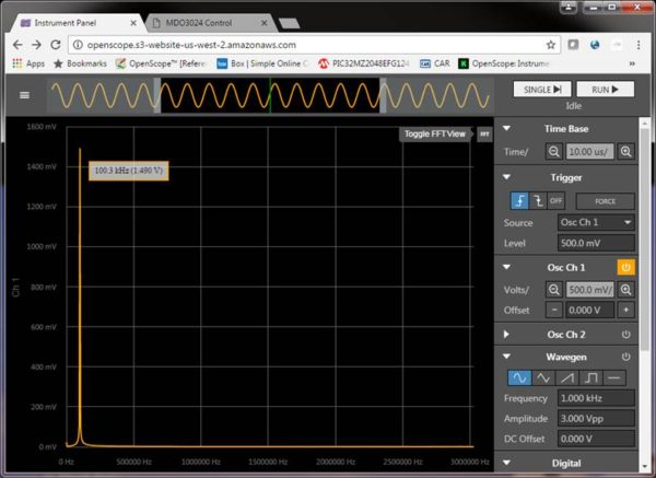
But let’s take this a little further. We implemented the ability to calculate an FFT in Waveforms Live [ this is a new feature that was recently enabled in the Beta Test of the Software]. If we take the FFT of the 100kHz waveform we should only see energy at 100kHz.

As you can see, we are pretty much dead on at 100kHz, and there is no energy at any other frequency. In fact, extremely clean!
Another very comforting observation is that there is no energy at 303kHz! This is the frequencies our PWMs run at, and we are running 4 of them with no energy there at that frequency. Our filtering of the PWMs is clearly working, keeping the PWM out of the analog signals.
Larissa: So the hardware is isolated well, so the PWM doesn’t affect the analog signals, and we are seeing exactly the type of clean signals that we would want. This works well for sine waves, but what about other types of waveforms?
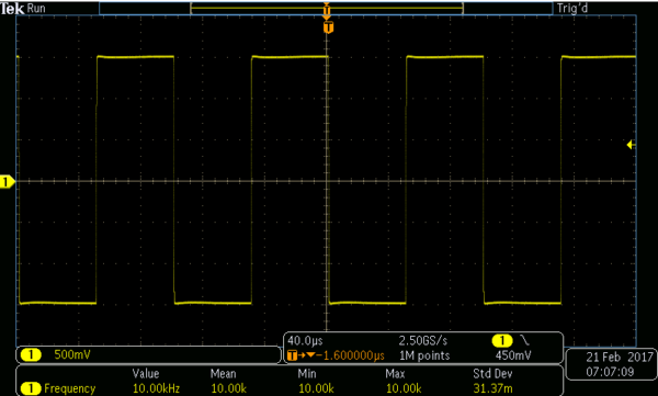
Keith: Let’s take this further: We know that a square wave is composition of every odd frequency above the base frequency. If we have our wave gen generate a square wave we should see the odd frequencies and not much else. We will use 10kHz square wave so we can easily several orders of composite frequencies in the FFT.
The graph is taken from my Tek scope, reading a square wave from the OpenScope Waveform Generator.
Compare this to the reading of the Oscilloscope from the OpenScope in Waveforms Live…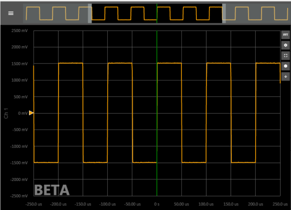
Larissa: It looks exactly the same as the Tek Scope.
Keith: Exactly. If we take an FFT…
You can see spikes at 10kHz, 30kHz, 50kHz, 70kHz, 90kHz…… Nice clean spikes way out there for 20+ terms.
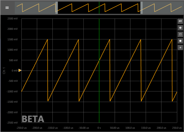
Larissa: Okay, so the square wave is clean. What about the sawtooth wave?
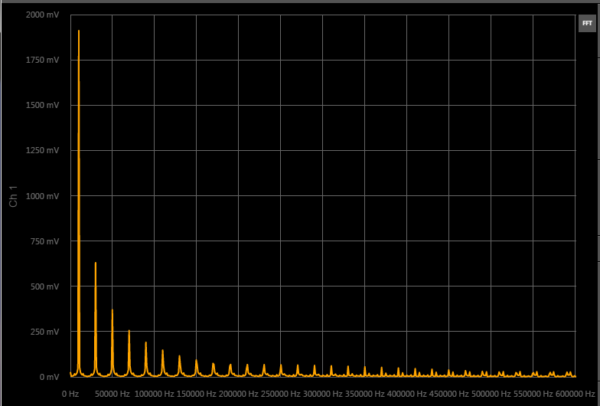
Keith: Okay, for fun… here’s the sawtooth wave and the FFT.
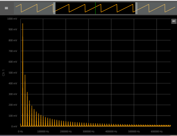
You’ll see spikes on each successive order, just as expected. Nice and clean.
Larissa: Okay, point proven. Sine, square and sawtooth all look really clean. Anything else we should ask?
Keith: You might ask, what exactly is going at those higher frequencies? Well, there seems to be some low level energy up there. That is really aliasing in the FFT due to the sampling rate. Remember, I am sampling at 6.25MS/s and at 500kHz I am only getting 12.5 samples per period.
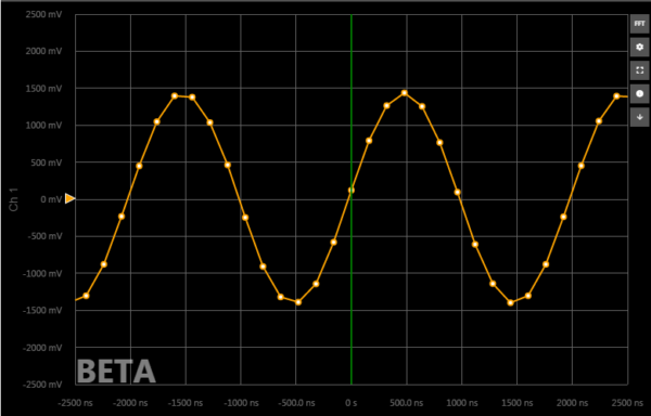
Here is a 500kHz sampled waveform at our 6.25MS/s, sampling effects are clearly visible.
I would refer you back to our 100kHz sine wave FFT, where there is no higher frequency components in the waveform (as opposed to a square or saw tooth waves where high composite frequencies exist)
Here you can see we are clean to well above 3MHz. There is no aliasing up there, because there is no frequency components up there.
As a result of looking at the FFTs, we can conclude that we have good separation from our digital circuits and our analog circuits, that we don’t have induce external energy and our circuits are working well.
Larissa: Is this the place you introduce our KickStarter stretch goal, of a Bode plot?
Keith: Yes, because they are so useful.
Bode plots are generated by stimulating a circuit with a sine wave and then looking at the resultant waveform, both in magnitude and phase. To do a good Bode plot you take the FFT of the input and compare it to the FFT of the output and plot the magnitude differences. Most Bode plots will plot magnitude in db. Most oscilloscopes are rated at their -3db attenuation point. The rule of thumb is that the maximum useful frequency a scope is good for is 1/5 it’s rated -3db frequency and 1/5th it’s sampling rate. So if you had a 5MHz scope, you could measure a 1 MHz wave. Or if you sampled at 5MS/s, you could reasonably measure 1Mhz. But this assume a typical 1st order drop off of the frequency. The OpenScope exceeds 2.5MHz at -3db, but drops off more closely to a second order cutoff. The OpenScope’s analog circuits are useful up to 1 MHz, and with a sampling rate of 6.25MS/s also meets the 5:1 sampling criterial to be useful at 1 MHz. Here are the Bode plots for the analog input of the OpenScope.
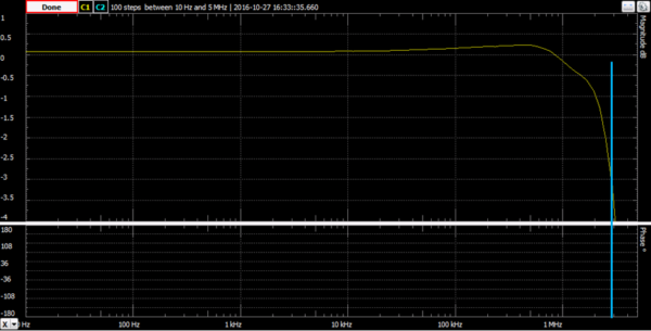
The worst case condition is unity gain (0db) through the analog inputs. As you can see the OpenScope is flat within 0.5db up to 1 MHz and drops off sharply to almost 3 MHz at -3db.
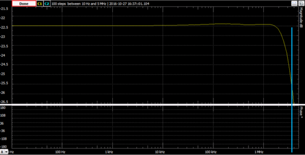
Here is the best case condition, the OpenScope operating at a gain of 3/40th (-22.5db). Here we are flat well within ¼ db up to nearly 2MHz and then very sharply dropping off to a -3db at 3.5 MHz
Larissa: That makes sense. What would be your parting answer to, “How good is the analog on the OpenScope?”
Keith: Rule of thumb would put the OpenScope usefully measuring 500kHz (2.5MHz at -3db / 5); but because of the very sharp cutoffs, the OpenScope is actually useful to measuring up to 1 MHz. The 6.25MS/s sampling rate being more of a factor than then analog circuits. So in summary? I would say, it’s pretty good, it will get you through most projects up to audio speeds and because we are using the microcontroller so well, the board cost is cheap enough to not break your pocketbook.
Larissa: Thank you, Keith!
Go and visit our Kickstarter Campaign and make sure to ask questions in the comments!
Hey its a great article.
Interview with the engineer is a great concept. I came across most of the new concept to know about its very informative article and easy to understand.