

…Who are you going to call?
For a lot of people, Ghostbusters may seem like the only option they have available to them. In fact, that is very much the way that I felt when I was working a new Pmod library and things just didn’t seem to be working out the way I expected them to. But then, I glanced to my left and saw…
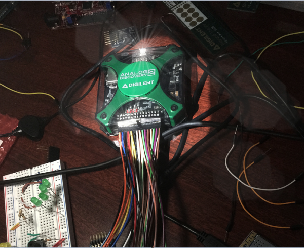
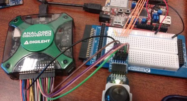
The Analog Discovery 2! But alas, what can it do to help me solve my problem? Especially when I’m not even sure what my problem is to begin with.
The biggest thing is that the Analog Discovery 2 (or AD2 for short) is an oscilloscope — a device that can measure and display the electrical behavior of a device. This means that with the appropriate knowledge of what sort of places we need to probe on the device, we can get a good picture of how it is operating electrically; this is something we can’t normally do by looking at it with the naked eye.
Was anyone able to #guessthecircuit yesterday? How many of the four did you guess correctly? #AnalogDiscovery2 pic.twitter.com/i7RxpqwsJK
— Digilent Inc. (@DigilentInc) June 10, 2016
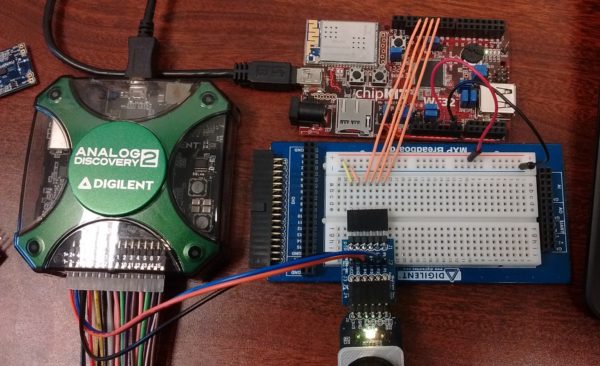
For my project, I was working on creating a library for the new PmodJSTK2, but was getting some inconsistent results when I sent a command to the joystick or read some data from the joystick. Sometimes everything would work exactly as I expected, and other times I seemed to be getting a bunch of nonsense. Because I was using SPI to communicate back and forth between the WF32 and the PmodJSTK2, I figured that would be a good place to observe all of the electrical signals to see if I could spot anything suspicious.
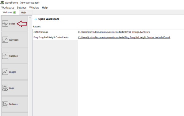
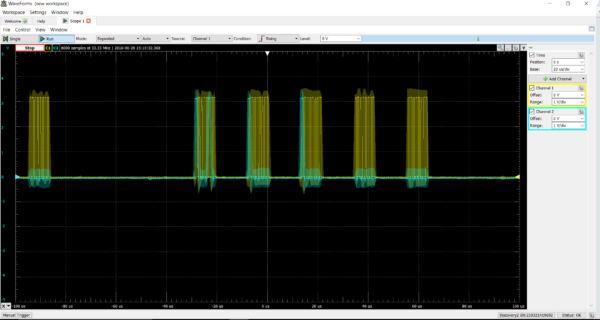
After following Kaitlyn’s guide for installing Waveforms 2015, I clicked on the “Scope” button (since that made the most sense for using an oscilloscope). Then I connected scope channels 1 and 2 to the data following to the PmodJSTK2 and to the clock that dictates how fast the two devices communicate, adjusted the time scale so I could reasonably see what was happening (since they communicate very fast with each other), and hit “Run” to start the oscilloscope.
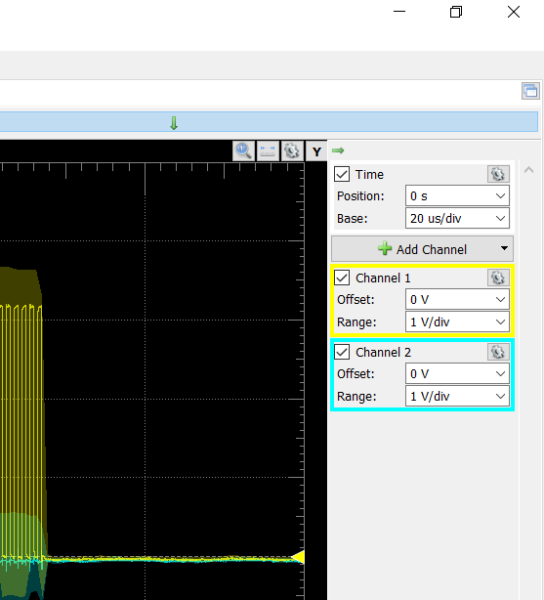
And soon it was running! However, I quickly found that while I could stop the oscilloscope and look at the information on the screen, it was rather tedious to manually calculate any time or data differences that were present. Plus, I also wanted to be able to view both data lines, the clock, and the enable line simultaneously, rather than being forced to pick just two of them.
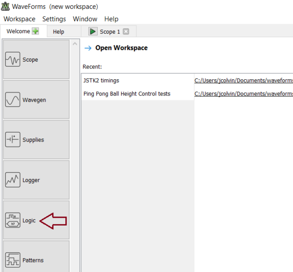
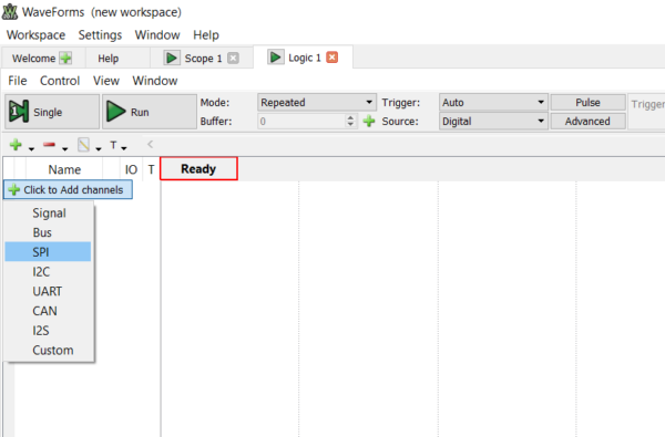
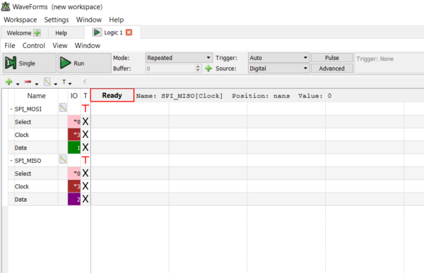
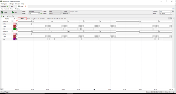
As I was verbally lamenting about my problems, a co-worker of mine decided to take pity on me and suggested that I use the Logic Analyzer tool inside of WaveForms 2015. Sure enough, along the left-hand side of the main window, there was a button labeled “Logic”. After clicking on that, I was brought to the Logic Analyzer page where I could add a new channel, choose SPI, and set which of the numbered AD2 pins are measuring which SPI communication line. I added a second SPI channel so that I could measure the data lines going both to and from the PmodJSTK2 simultaneously, set my time base, and clicked run.
I could immediately tell that the Logic Analyzer was definitely the tool I was needing to use, instead of the oscilloscope. All of the transitions were crisp and clear, which makes sense considering that the oscilloscope focuses on measuring an accurate voltage and captures all of the transitions as well as any oscillations between transitions. In contrast, the Logic Analyzer instead looks to see if the measured voltage has crossed a high or low threshold, since it is a digital logic analyzer.
It was only because of this Logic Analyzer that I was able to notice a strange timing error where the SPI communication would suddenly be cut off part way through a message. Digging into the problem a little bit further revealed that an additional delay was needed between the final byte of data being transferred and the signal to stop communicating over SPI. This was then incorporated into the embedded firmware so other users would not have to worry about it.
So, as tempting as it might be to look up Bill Murray’s number to give him a call, there may be something close by that can help you figure out the solution to your problem. For me, that something was the Analog Discovery 2. What do you use to help solve your problems?