

Welcome back to the Digilent Blog!
Inter-integrated-circuit, more commonly known as I²C (generally pronounced I-squared-C), is a communication style originally developed by Phillips Semiconductor (now NXP Semiconductor). Its design allows multiple components to be able to talk to each other on the same data line, making it widely used in a variety of systems, including Pmods. As a fan of Pmods, I’m in favor of learning how you can communicate with them and get them what you want to do. Let’s find out more.
One of the reasons why this protocol is so widely used is that it uses only two communication wires: a serial data line (SDA) and a serial clock line (SCL), which are both natively held in a logic high position through the use of pull-up resistors. Many other communication protocols, such as SPI, require more I/O pins to function, as well as additional pins for each subsequent component that is added to the communication bus (the wires that allow multiple devices to talk to each other). A “master” device can easily choose to talk to just one of the many “slave” devices by issuing a start condition, sending out the address of the device that it wants to talk to as well as an indicator of whether it wants to read from or write to the device.
If the device that the host board is calling is on the line (pun intended), that device will respond with an acknowledge (ACK) bit by pulling the SDA line low. The slave device will then listen for the next command while all of the other devices that are also on the bus wait for another start condition before listening for their address again. After receiving an ACK, the master can then tell the listening device which register address within the on-board chip that it wants to read from (or write). Once an additional ACK is received, confirming that particular action is permissible, data transmission between the two devices can occur. Once all of the desired data transfer has occurred (as determined by the user’s preferences) the master may then issue a “restart” (pulling SDA low while SCL is idling high)to start a fresh communication session or should release the SDA line while SCL is high as its “stop” condition.
However, this all presumes that everything goes smoothly and the receiving device acknowledges the 8 bits of data by pulling the serial data line low. But what about when the data line is instead left at a high voltage state from the pull-up resistor? This would indicate that the data transfer was not acknowledged, implying that something was wrong with the data. Naturally, what exactly went wrong is dependent on when the NACK (a negative-acknowledge character) was read by the receiving device. The table below illustrates when a NACK might occur and what you could do about it.

Within the I²C protocol, the master device always retains control of the serial clock, driving the line low to indicate to the transmitting device that it should place a bit on the SDA line (blue bars) and allowing the line to go high telling the receiving device to read the bit on the SDA line (green bars).
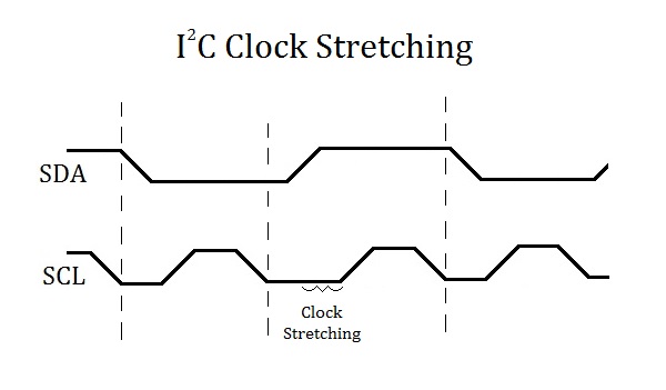
But because the only feedback that a transmitter receives is an ACK or NACK after 8 bits have already been transferred, there is no way for the master device to instinctively know if it is pulsing the SCL line too quickly for the slave device to place or read bits to or from the data line. Luckily, the I²C protocol mitigates this problem through a feature called clock stretching.
Clocking stretching is the ability of a slave device to continue to drive the serial clock line low after the master device has already released the clock line to be pulled up to the high voltage state. This is used to guarantee the slave device enough time (as determined internally by the slave device) to read or prepare the next bit before the clock “ticks” again. In accordance with this, the master device waits for the serial clock line to actually reach the high voltage state before delaying a set amount of time (to ensure the receiver reads the bit on the data line) and subsequently driving the SCL line to a low voltage state.
With the feature in I²C of multiple devices being able to connect to the same I²C bus, there is a possibility that two masters might initiate start condition at the same time or have multiple slave devices that respond to a single address. As there is no way for any of the components on the line to instinctively “know” that there is another device also using the data line, this raises the possibility that a bus collision (literally) might occur.
To avoid this breakdown in communication, all devices that are currently using the SDA line will go through arbitration on every bit to determine if they have control of the line. This is done by having each device that may be trying to use the data line place their bit of data as they normally would (driving SDA low or leaving it to idle high) and then reading the voltage level on the line to see if it is what the device expects. If a device sees that the line has been driven low when it expects it to be idling high, it will conclude that another device must also be using the SDA line and subsequently relinquish control of the data line, losing arbitration.
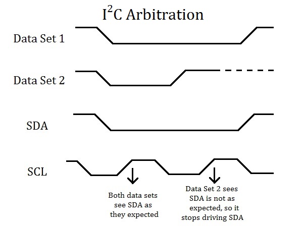
The second device, seeing that the voltage level is as it expected, will continue transmitting its message although it will also continue to check the line after each bit in case there is another device that has happened to exactly match its bit values so far. When a master device loses arbitration, it will relinquish control of both the SDA and SCL line and wait for a stop condition before attempting to transmit its message again.
But what about if two devices match each other’s bit values for the entire duration of the communication session from the start bit to the stop bit? I’ll leave you with a question of my own for you to answer: is this actually a problem for my system?