

Recently, National Instruments released a set of example labs designed to show you how you can get the full use of your Analog Discovery 2.
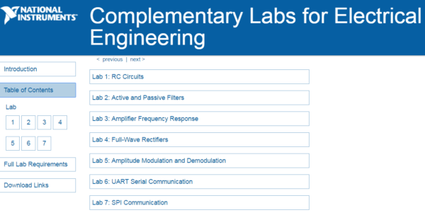
Below, we cover each lab, the tools it uses, and concepts that can help you teach your students.
Lab 1: Resistor-Capacitor Circuits
Designed for an introductory circuits course, Lab 1 covers how RC circuits respond to DC and AC voltage sources, and how that behavior translates into high-pass and low-pass filter design. Students work through the theory analytically, verify it in Multisim Live, then wire up the circuit themselves in Fritzing and on the Analog Discovery 2, using the cursors on the Oscilloscope to measure the charge/discharge time constant directly. For a challenge, students combine the high-pass and low-pass stages they’ve built to design their own band-pass and band-stop filters.
For this lab, students will need:
- An Analog Discovery 2
- A resistor, capacitor, breadboard, and breadboard wires
- All of which can be found in the Analog Parts Kit
- A Multisim Live Premium account (Free for a limited time!)
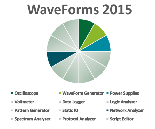
- WaveForms (A Quick and Free Download)
Lab 2: Active and Passive Filters
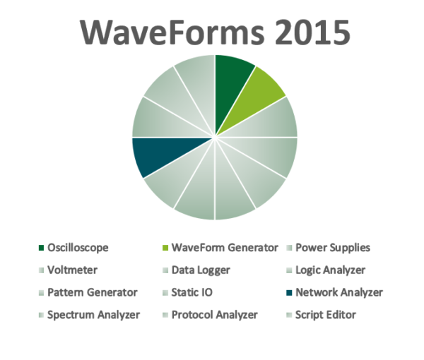
Lab 2, aimed at an intermediate circuits course, builds on Lab 1 by introducing transfer function analysis and comparing passive vs. active filter designs, including how moving to higher-order filters changes both the transfer function and the filter’s behavior. Using the Network Analyzer, students swap components in and out to see the frequency response shift in real time, then close out by comparing Butterworth and Chebyshev filter characteristics against each other.
For this lab, students would need:
- An Analog Discovery 2
- Some resistors, capacitors, an op-amp, a breadboard, and breadboard wires
- All of which can be found in the Analog Parts Kit
- A Multisim Live Premium account (Free for a limited time!)
- WaveForms (A Quick and Free Download)
Lab 3: Amplifier Frequency Response
Intended to be included in an intermediate circuits or electronics course.
Lab 3: Amplifier Frequency Response is designed to teach students about the characteristics of amplifier circuits. Just as in passive and active filters, analyzing the frequency response is an important step in designing amplifier circuits. This lab will go through two types of amplifier circuits: a CE amplifier designed with an NPN transistor, and an inverting amplifier designed with an op-amp.
This lab also uses Multisim Live and WaveForms. For this lab, students will use the power supply and waveform generators to provide the DC and AC input, and an oscilloscope and network analyzer to discover the output. All of these tools are available to them on one device, the Analog Discovery 2.
For this lab, students use 4 of the 12 tools: the waveform generator and power supplies for inputs, and the network analyzer and oscilloscope to measure the results.
For this lab, students will need:
- An Analog Discovery 2
- Some resistors, capacitors, an op-amp, an NPN transistor, a breadboard, and breadboard wires
- All of which can be found in the Analog Parts Kit
- A Multisim Live Premium account (Free for a limited time!)
- WaveForms (A Quick and Free Download)
First, students learn the basics of a common emitter (CE) amplifier, including the frequency response and the low critical frequency, mid-range, and high critical frequency.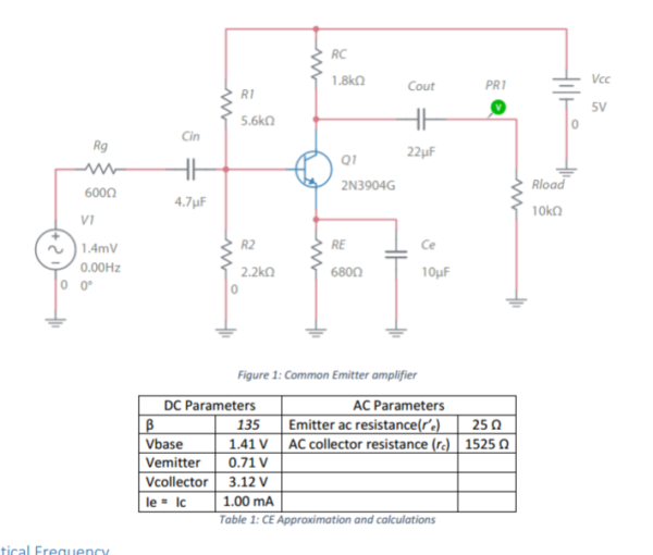
They then simulate the circuit with Multisim Live.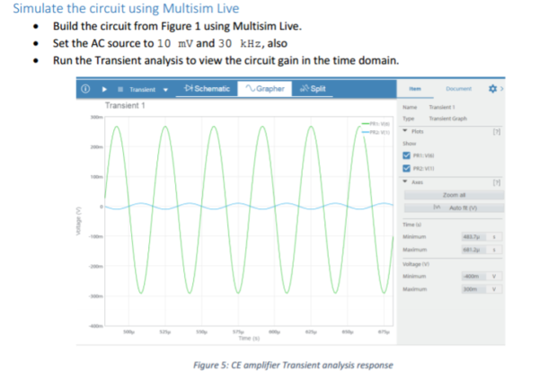
Then they explore an op-amp open-loop filter and inverting amplifier characteristics with Multisim Live.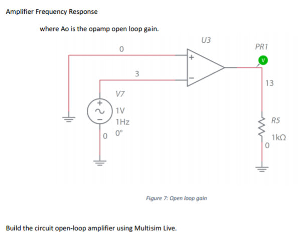
They also explore the inside of an op-amp and the transistors that make it work the way it does.
Then they continue to use Multisim Live to investigate slew rate.
Finally, the lab goes into building the circuit:
First, students must build the CE circuit and connect the Analog Discovery 2. The power supplies and waveform generator provide input, and both oscilloscope channels are used to measure the input and output.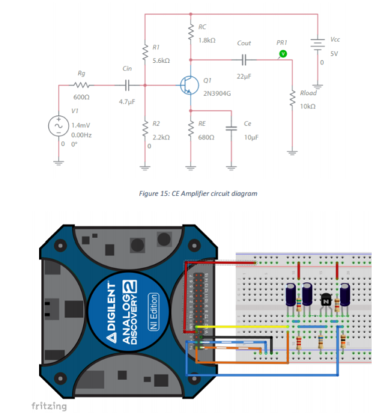
Along with analyzing in the time domain, the network analyzer is used to measure the frequency response, which students are asked to compare with their simulation response.
Next, they analyze the op-amp inverting amplifier in a similar fashion.
More advanced student can be challenged by considering how they would change their amplifier design in high-speed vs low speed applications.
They can use Multisim Live to build and simulate the circuits, and then use the Analog Discovery 2 and WaveForms to examine their actual behavior. The Network Analyzer provides students with a quick way to verify their circuit behavior and adjust components if needed for more of a rapid prototyping experience.
Lab 4: Full Wave Rectifiers
Suited to an introductory electronics or power electronics course, Lab 4 introduces full-wave bridge rectifiers. Students simulate and build one, then characterize diode behavior by measuring I-V curves. This is the first lab in the series to bring in LabVIEW alongside WaveForms, using the Digilent WaveForms VIs to plot the relationship between diode current and voltage drop.
For more on plotting I-V curves, see our curve-tracer post.
LabVIEW is Digilent’s graphical development environment for engineers and scientists. It lets you visualize, build, and code measurement routines without traditional text-based programming.
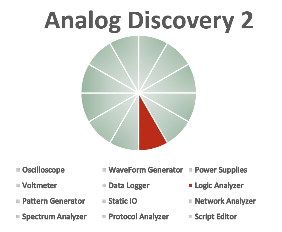
For this lab, students will need:
- An Analog Discovery 2
- Some resistors, capacitors, diodes, a breadboard, and breadboard wires
- All of which can be found in the Analog Parts Kit
- A Multisim Live Premium account (Free for a limited time!)
- WaveForms (A Quick and Free Download)
- LabVIEW 2015 or Later (available from Studica)
- Digilent WaveForms VIs (A Free Download)
Lab 5: Amplitude Modulation and Demodulation
Built for an intro communications course, Lab 5 introduces classical AM theory in both the time and frequency domains, along with the basics of the FFT and how modulation index shapes an AM signal. Students use the Spectrum Analyzer to view the frequency components of their signals, then move into AM demodulation using a LabVIEW envelope-detection VI.
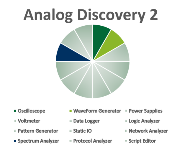
For this lab, students would need:
- An Analog Discovery 2
- Jumper Wires
- WaveForms (A Quick and Free Download)
- LabVIEW 2015 or Later (available from Studica)
- Digilent WaveForms VIs (A Free Download)
Lab 6: UART Serial Communication
Aimed at a microcontroller or embedded systems course, Lab 6 introduces serial communication through UART, covering start bits, stop bits, synchronization bits, and baud rate using the Analog Discovery 2’s Logic Analyzer to capture and decode signals sent from a Digilent uC32 via LINX and LabVIEW. Students set up their own UART transmission parameters and, for a challenge, decode an ASCII character transmission.
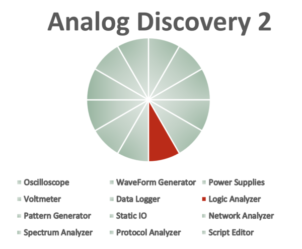
For this lab, students would need:
- An Analog Discovery 2
- Digilent uC32 or other LINX-supported microcontroller
- Jumper wires
- LabVIEW 2015 or Later (available from Studica)
- Digilent WaveForms VIs (A Free Download)
- Digilent LINX
Lab 7: SPI Communication
Also designed for a microcontroller or embedded systems course, Lab 7 wraps up the series with SPI communication, using the Logic Analyzer alongside LabVIEW and LINX to send, receive, and validate SPI data from a microcontroller. Students learn how the clock, slave select, MOSI, and MISO signals work together during communication, and for a final challenge, decode ASCII characters and explore basic encryption.
For this lab, students will need:
- An Analog Discovery 2
- Digilent uC32 or other LINX-supported microcontroller
- Jumper wires
- LabVIEW 2015 or Later (available from Studica)
- Digilent WaveForms VIs (A Free Download)
- Digilent LINX
Now that you’ve seen a preview of all seven labs, download them and start exploring the concepts for yourself. Together, they cover topics ranging from introductory RC circuits and filters to amplifier analysis, rectifiers, analog communications, and serial communication protocols, giving students a practical way to build hands-on measurement skills with the Analog Discovery 2. If you are interested in the tools that the Analog Discovery 2 has to offer, more information can be found on its Wiki Page.


