


Editor’s Note – In this series, we will take a behind the scenes look at how an engineer tackles a project from beginning to end. What challenges will come up? How can we face problems and come up with solutions? Aside from project completion, what are successes that we can celebrate along the way?
- Post 1 – Introducing Ryan
- Post 2 – Initial Considerations
- Post 3 – Designing a Zmod Peripheral
- Post 4 – Setting Up SYZYGY DNA
Now that the DNA data has been set up (discussed in the previous post), it’s time for the data to be written inside the flash of the attiny44a microcontroller available on the designed boards. The firmware which has been loaded into the attiny to perform SYZYGY® operations was acquired from the SYZYGY® GitHub.
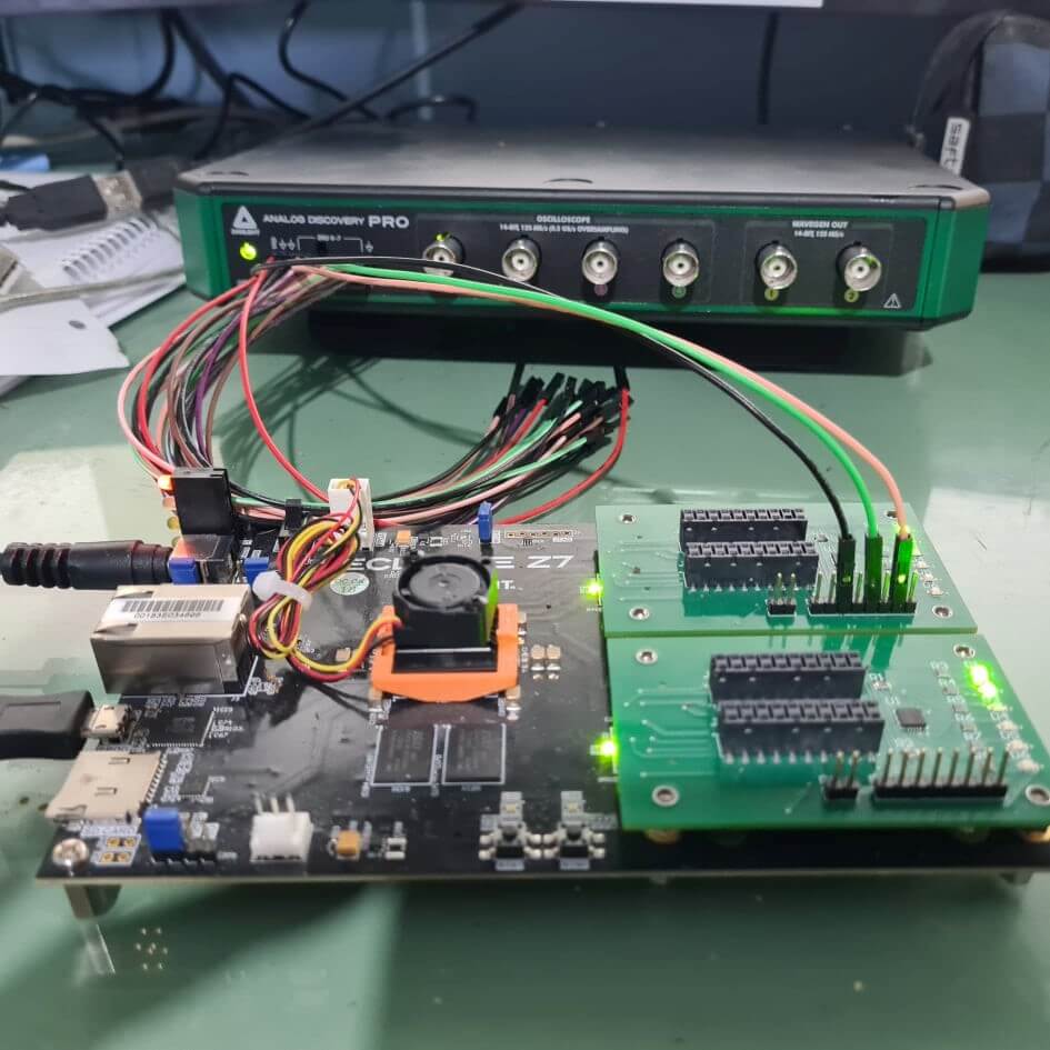
Now, it’s time to bring out the ADP3450! As illustrated in Figure 1 below, is the ADP connected to the designed test Zmod boards which are mounted on the Eclypse Z7. The connections are the ground and the two I2C data signals (SCL and SDA) going to the microcontroller (note that the microcontroller is powered by the 3.3V on the Zmod connector provided by the Eclypse Z7).
Once the connections were set up and the ADP3450 connect to the PC, WaveForms was opened. The protocol option in Waveforms has been used to communicate via I2C to the microcontroller. The I2C 7-bit address of the microcontroller depend to which Zmod connector the board is connected to. Zmod connector A on the Eclypse Z7 provides 7-bit I2C address 0x30 (Hexadecimal) while Zmod connector B provides 7-bit address 0x31. It is also important to note that the attiny microcontroller on the Zmod is, according to its firmware, set up as an I2C slave.
The I2C tab on WaveForms protocol panel has been selected. Since we need to communicate to the attiny as an I2C master, The Master tab has been chosen. Figure 2 below illustrates the I2C master setting applied to the WaveForms software.
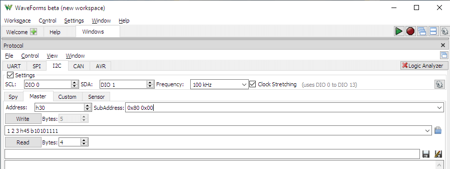
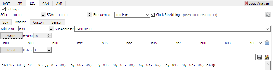
The digital outputs DIO 0 and DIO 1 have been used for I2C communication! Also note that a ground connection is necessary for I2C to function properly. The DNA data in the Excel sheet has been copied to a row with the low byte of the address of every byte under the data so as to make it easy to copy and paste to the WaveForms software (Figure 3).

It is important to note that the DNA data begins on 16-bit address 0x8000 in the flash memory of the attiny on the Zmod. The DNA data is copied 16 bytes at a time into the write panel of WaveForms and is written by pressing the write button. Important: after each of the 16 bytes are written it is important to update the address!
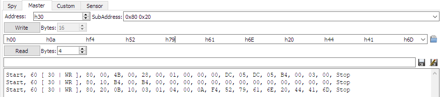
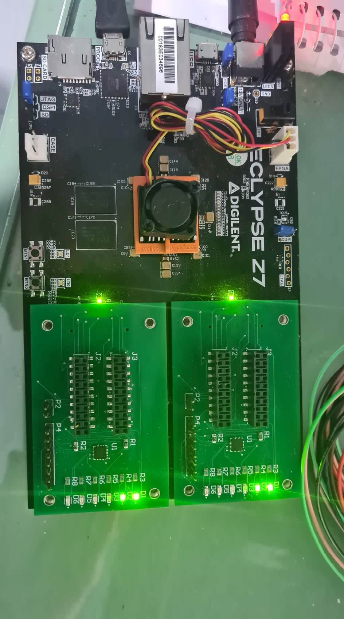
Once the data has been written, WaveForms also has a read function, which is very convenient in this case to confirm the correct data has been written in the correct addresses. Once the DNA data has been written and confirmed by reading back, we are ready to begin. Switching off and on again the Eclypse should lead to the SmartVIO controller of the Eclypse to enable the VIO voltages for the Zmod or Zmods. This will be confirmed by the small led behind the Zmod connector on the Eclypse Z7 to go ON as shown in the image below.
Now that the Zmods have been correctly configured, the next step is to analyze some signals outputted by the ZYNQ 7000 chip which are routed to the Zmod ports! This will be done using the very handy Analog Discovery PRO (ADP3450) and will be discussed in detail in the next post or two!