Welcome back to the Digilent Blog!
It is time to check out another set of the Digilent Pmods! Last time, we looked at a subset of the input focused Pmods, the analog-to-digital converters. Today, we’re going to take a look at more of the input Pmods, most of which incorporate ADCs into their design structure. These ten peripheral modules are all inherent sensors, reporting the temperature, location, light level, or movement without the user needing to physically interact with them.
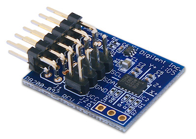
Within our convenient “movement subsection” reside three peripheral modules: the PmodACL, the PmodACL2, and the PmodGYRO. Both the PmodACL and PmodACL2 are 3-axis accelerometers. An accelerometer is a type of device that is able to measure the static acceleration of gravity (great for tilt sensors) as well as dynamic acceleration if the device is purposefully moved (great for everything else). The ACL is a digital accelerometer which provides up to 13 bits of resolution through either I2C or SPI for each of the three axes. This Pmod also is able to detect both single and double taps from any direction as well as whether or not the device is in free fall. Although one has to wonder: what does the PmodACL think to itself when it realizes that it is in free fall? You can always find out by checking out the contents in it’s 8-bit 32 word deep FIFO buffer. This allows the module to store data samples until you are ready to receive them.
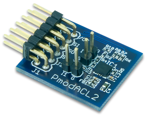
The PmodACL2 is slightly different than the PmodACL in the fact that it uses a MEMS (micro-electromechanical systems) accelerometer to collect the information rather than a purely capacitative accelerometer like the ACL. It also includes a 8-bit 512 word deep FIFO buffer so that you can access the 12 bits of information about the three axes, as well as the temperature on the chip through SPI. You can also set up the ACL2 so that it only reports a single byte (8 bits) of the information to you for an easy conversion as well as ignoring the temperature if that is not relavent to your application. It’s pretty sweet.
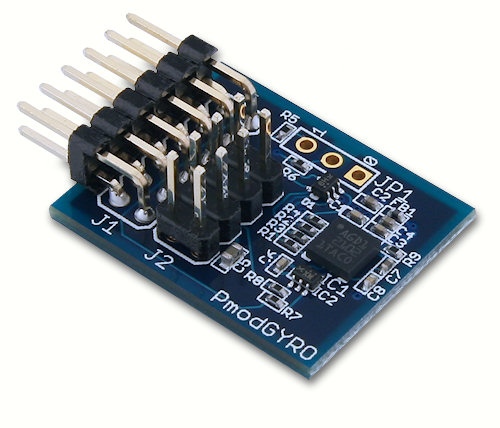
Gyroscopes also measure movement that occurs in a particular direction. Don’t confuse them with an accelerometer though; they are different. Speaking in a broad sense, gyroscopes measure if an object is being tilted in a particular direction while accelerometers measure if an object is moving in a particular direction. The PmodGYRO is a 3-axis gyroscope, allowing it to sense if the Pmod is being tilted in any of the three cartesian coordinates (the x, y, and z directions), as well as giving it a very stable axis so that zero value output of the Pmod when there is no tilt is consistent. Each of the three directional ouputs are available as 16-bit outputs in addition to a an 8 bit temperature output from the on-board temperature sensor. These four sets of data can be stored in a 16-bit 32 word deep FIFO buffer to allow you to access the data whenever it is most convenient for you.
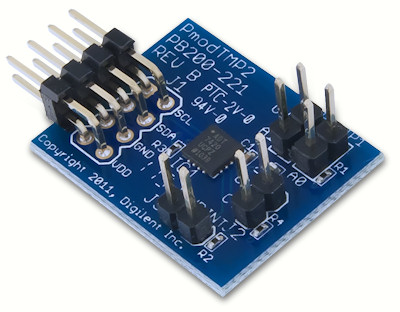
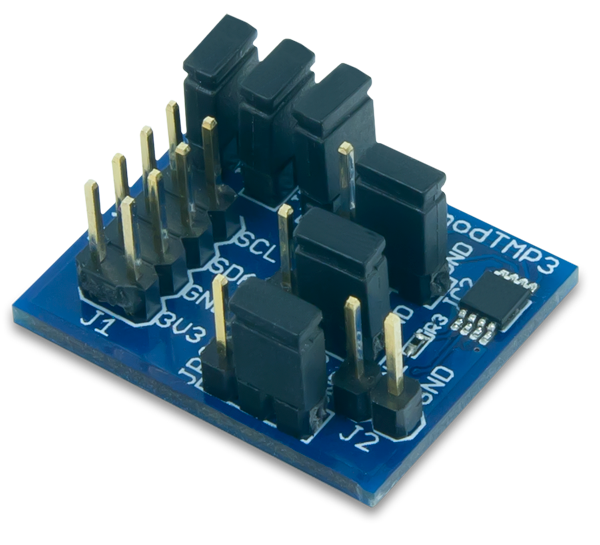
There are also a couple of Pmods that solely measure the ambient temperature if you need a higher resolution for a more accurate temperature. These are the PmodTMP2 and PmodTMP3. Both of these Pmods have an operating range of approximately 300 degrees F (over 150 degrees C), making them ideal in the vast majority of applications. The TMP2 is able to report the temperature over the I2C interface anywhere from a 9-bit resolution (including the sign bit) to 16-bit resolution (including the sign bit) with an average conversion time of 240 ms. The TMP3 can report over the I2C protocol anywhere from a 9-bit resolution (including the sign bit) to a 13-bit resolution (including the sign bit) with conversion times ranging from 30 ms to 240 ms, respectively.
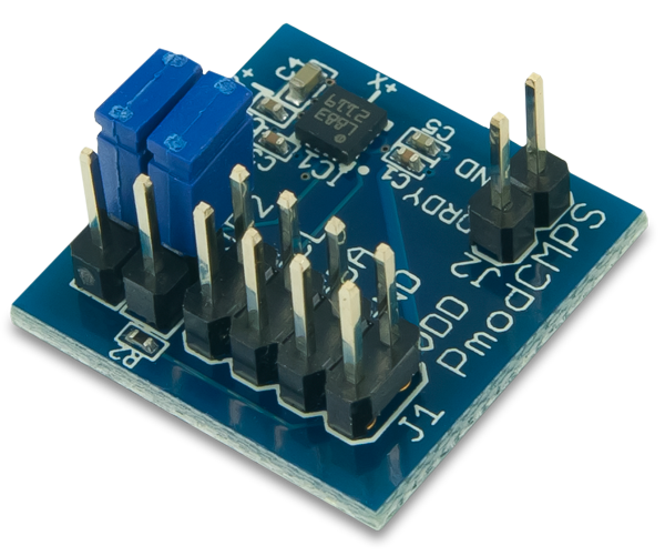
In addition to movement and temperature based Pmods, Digilent offers Pmods that are suited for exploration expeditions. The PmodCMPS uses a 12-bit ADC to send relevant magnetic data in all three axes to the host board through the I2C protocol. With its anisotropic magnetoresistive technology (AMR, which is a property of a material where its resistance changes based on the angle that a magnetic field intersects with the electric current flowing through the material) allows for precise measurements in each axis with minimal interference from the other two directions.
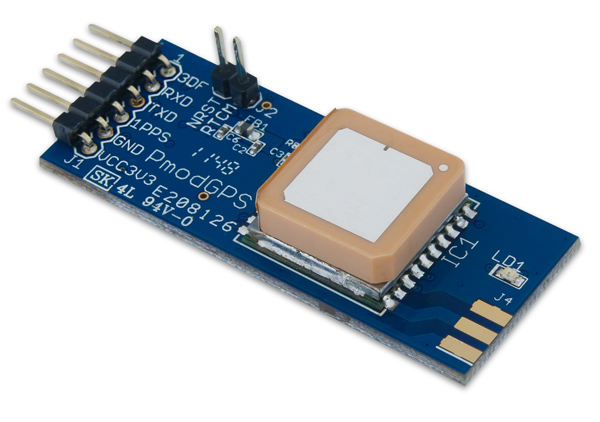
But just knowing what direction you are facing without knowing where you are is not terribly helpful. The PmodGPS allievates this program by acting, not surprisingly, as a GPS. By using its UART interface, the PmodGPS is able to output several “sentences” of information including the current location, what time the location was calculated, how many satellites were used to determine the position, as well as a variety of other details. When the PmodGPS is used in conjunction with flash memory this module is able to act as a data logger, recording a series of locations up to a rate of ten times a second. With the PmodGPS, you’ll never be lost again.
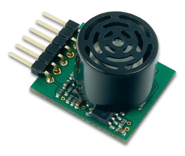
Another input based peripheral module is the PmodMAXSONAR. You have seen this Pmod mentioned in a couple of past blog posts by Larissa and yours truly where we explained that this ultrasonic Pmod is capable of detecting objects over 20 feet in front of it with a one inch accuracy. The distance detected by the PmodMAXSONAR is able to be communicated to the host board through UART, an analog signal, or a PWM signal.
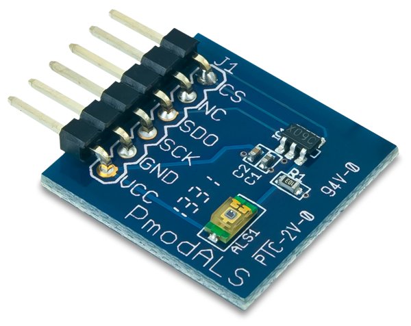
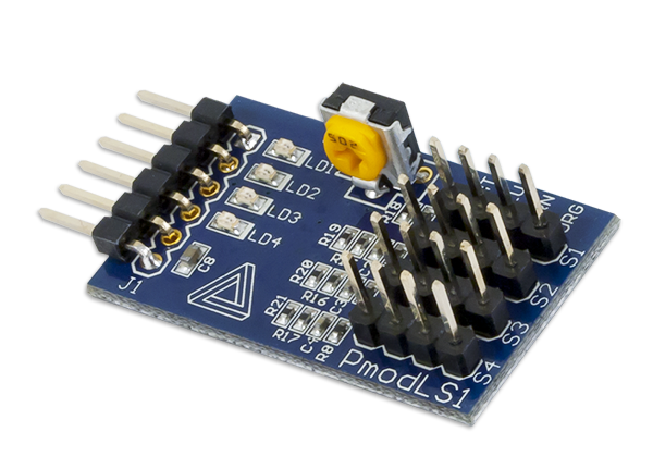
And finally, we have our two light sensor modules, the PmodALS and the PmodLS1. The PmodALS is an ambient light sensor that reports back to the system board via SPI the 8 bits that represent the current surrounding light level with a 0 for no light and 255 for the maximum detectable brightness. The PmodLS1 is designed to have up to four infrared sensors attached to it. The infrared sensor consists of two parts: a infared LED and a infared sensitive transistor. With this combination, when the infared LED shines on a reflective material the transistor will detect it and have the PmodLS1 report with the appropriate GPIO pin a high voltage. If the infrared LED shines on a non-reflective material, such as black electrical tape, the transistor will not detect any infrared light, so that the LS1 will report a low voltage value on the appropriate pin. This functionality makes the PmodLS1 an ideal component for a line-following robot.
Despite the large number of Pmods™ that we have checked out today, we still have quite a few more to go, even within the input Pmods. So keep checking back in with the Digilent Blog to find out more about our extensive line of Pmods!

