

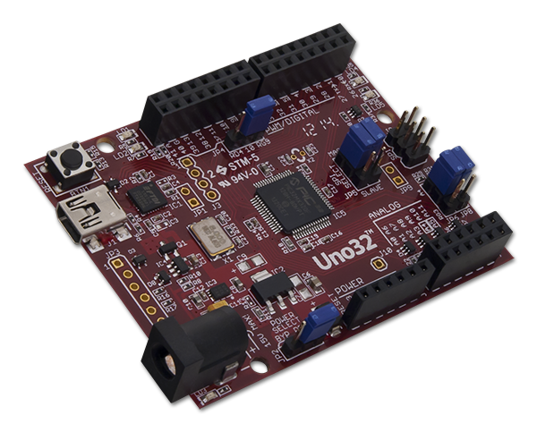
I really enjoy what I do here at Digilent. I get to work with some of the best tools available for students, professionals, and hobbyists alike. One of the things I like most is how easy it is to get your hands on a good quality microcontroller board, like the chipKIT Uno32.
But even once you get a good board, it will still need to be programmed. Now, if you’ve ever programmed a microcontroller in Assembly language, you know how elegant it can be to deal directly with the register values. It’s simple and easy to do and makes for some pretty fast code if you do it right. The problem is that the popular IDE formats, like MPIDE, are designed to be very user-friendly, so the coding language is high level (C/C++). That means that when the chip is programmed, there is some conversion that happens in the compiler to re-write your sketch into Assembly so the chip can process it. Along with the higher level language comes the ease of having more user-friendly pre-built functions, like digitalWrite(), but they have to be converted to Assembly and loaded along with your sketch. Anytime you use that function, the processor looks it up in its memory and executes it accordingly. This takes space in memory and a lot of processing time, which can be a problem if space or speed are an issue.
So how do we fix that? Is there a way to still use the user-friendly IDE and still have the speed and space of direct register manipulation? Why, yes! Yes, there is. And it is surprisingly simple.
The Microchip PIC32 chips use three registers on every I/O pin for reading and writing data. (Pins that pull multiple duty like PWM, I2C, or UART have more registers.) The first is TRISx, which sets the I/O direction of the pin and refers to the tri-state capability that allows the pin to be either output, input, or high-impedance (neither in nor out). Setting a ‘1’ in TRISx will set the corresponding pin to be an input and a ‘0’ will set it as an output. The next register is LATx and acts as a latch. If the pin has been set as an output in TRISx, you can then write a ‘1’ or ‘0’ as needed to the same bit position in LATx. This will set the logic state on that pin as either HIGH or LOW accordingly. The last register is PORTx, which is the input status of a pin set as an input using TRISx. You can read the data from here and process it as needed in your sketch. The standard IDE functions that map to these registers are pinMode() (TRISx), digitalWrite() (LATx) and digitalRead() (PORTx).
For a more in-depth explanation and some example code, check out my Instructable!