

Welcome back to the Digilent Blog!
As many of you know, it is possible with many types of displays, such as LCDs and LED displays, to create your own custom characters and, naturally, display them. However, to create your own characters, you need to be able to create a bitmap of how your character (or characters) look. We will be working with the PmodOLED and it’s corresponding library to create our own characters.
A bitmap is what it sounds like it is: a map made up of bits. These bits, which can either be a ‘0’ or a ‘1’ for ‘off’ and ‘on’, respectively, can be purposefully (or not so purposefully) arranged so that the on and off state reveals a picture. Typically, each character bitmap is 8 bits tall and 8 bits wide, for a total of 64 bits or 8 bytes. These 8 bytes that make up a single character, at least in our OLED library, are defined individually as 8 bit columns in hexadecimal.
For each of the 8 bit columns, the hexadecimal system is styled as 0x (to indicate that it is hexadecimal) and then a set of two number/letters between 0-9 and A-F. The 0-9 are the numbers that we use in the “normal” decimal system; the A-F make up the remaining six values (hence the “hex” in hexadecimal) corresponding to 10, 11, 12, 13, 14, and 15. The first value corresponds to the bottom four bits in the column where a ‘1’ only turns on the top bit and a ‘F’ turns on all four of the bits (1 + 2 + 4 + 8 = 15). Similarly, the second value corresponds to the top four bits of the column. With this in mind, the 8 columns for an “X” character might be designed as {0x81, 0x42, 0x24, 0x18, 0x18, 0x24, 0x42, 0x81}.
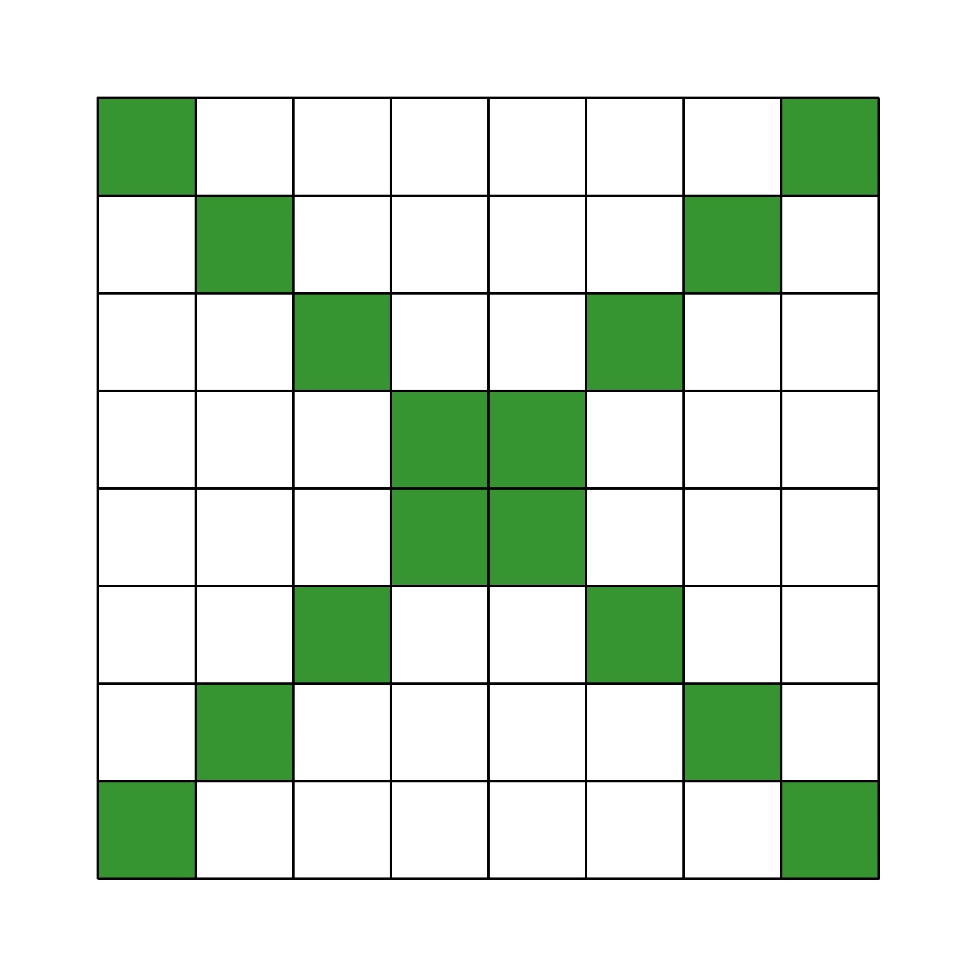
To visualize how your character might need to be designed, I recommend using a spreadsheet program like Microsoft Excel where you can easily fill in or blank out individual squares in order to get your desired pattern.
But despite knowing how to design a character, it is arguably more helpful to know how make that character available for your use within the code. To do this there are four things that we would need. We need to tell the program how many bytes each of our characters are going to be, how many characters we are defining in our custom font table, what the bitmap for each of those characters are, and use the library function to let the program know we have defined a custom character.
So, if we wanted to make a checkerboard pattern along with the “X” as new characters in our font table, we would need to type the following:
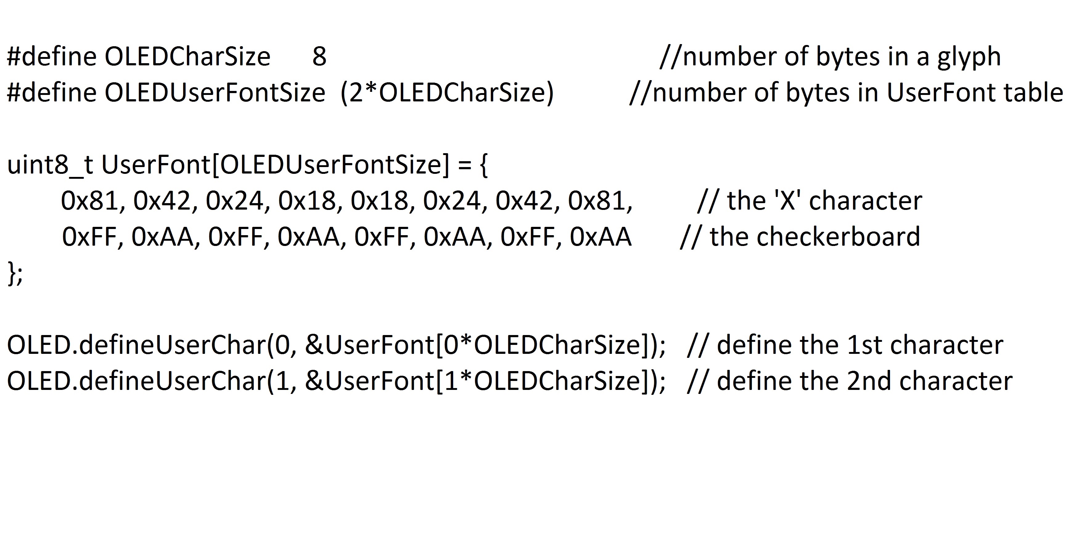
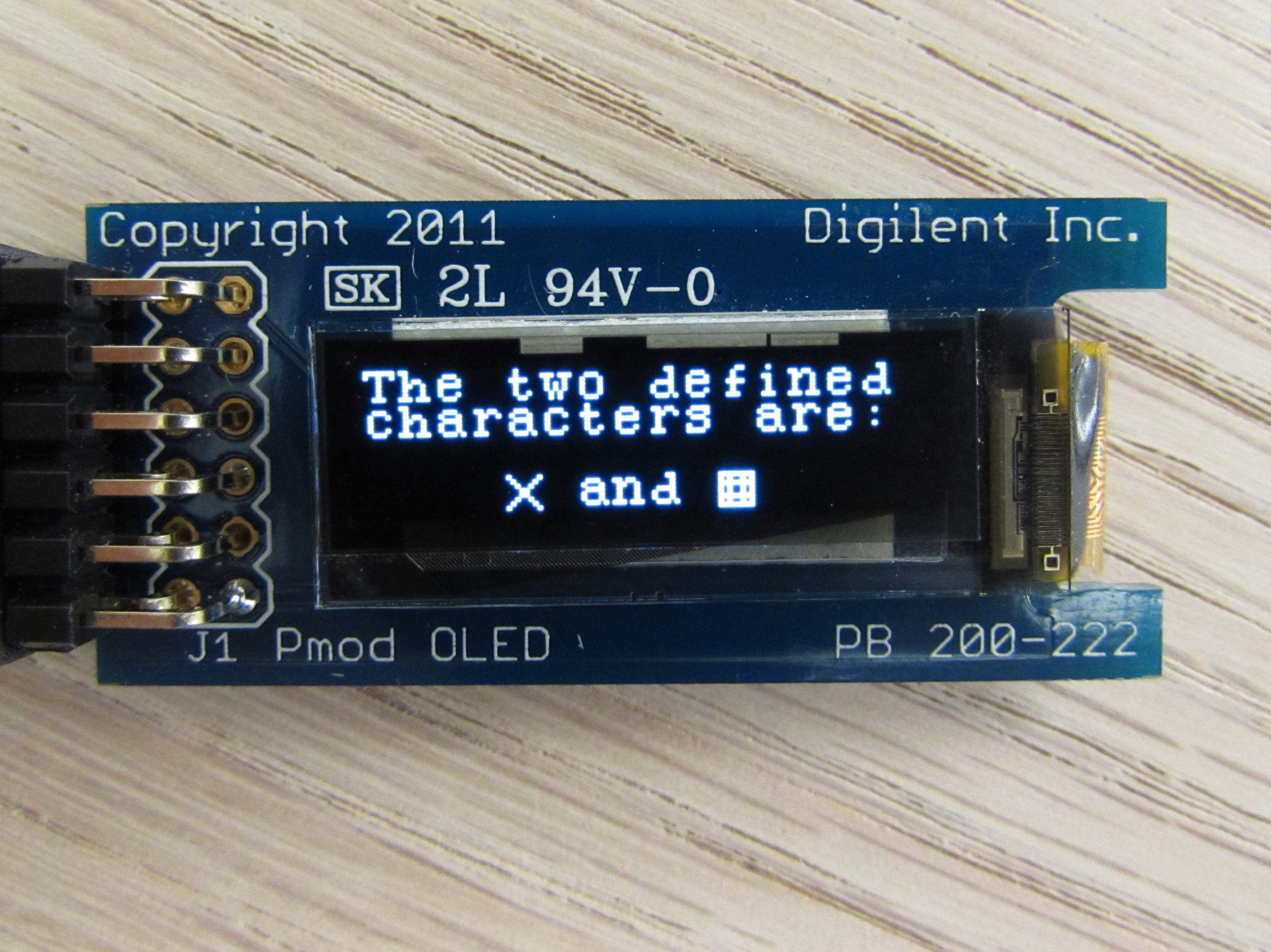
The code that I used to display what you see is available here.
However, you may be asking yourself, where exactly did our “OLED.defineUserChar” function define our characters to? What would make the most sense (and what actually happens) is that our custom characters get defined in a pre-existing font table. This table, known as an ASCII table, contains all of the “normal” characters that we can type with our keyboard are defined.
However, this table does not expand when we define our custom characters. Rather, one of the first 32 non printable characters in the ASCII table, such as “end of transmission” and “file separator” are redefined. Because these 32 characters do not actually “show up” on a page they are available to be written over in favor of our custom characters without detriment to the screen display.
One final thing before you go. Perhaps you want to create a display that will take up more than the 32 characters you have available to write over and you don’t want to be forced to redefine the letter ‘A’ to what you need for your display. To get around this dilemma, what we can do is create an array to hold our own bitmap. What this does is set aside a block of memory on our microcontroller to hold our “characters”.
The program will not know that these are characters, so we will not be able to place them with our predefined “putChar” function, but we can specify a size and have the library place the entire bitmap into the specified area with “putBmp”. With this code, you can create super cool images like the Digilent Logo!
If you have any trouble getting your PmodOLED up and running, be sure to check out this post on the Digilent Forum.
Let me clarify my point on LabVIEW and touch ready…
I mean that the concept of direct manipulation in LabVIEW,
of picking blocks and placing them and then wiring them together is more amenable to “touch-based development” than using a touch-based text editor to write code.
I am optimistic, that for many use cases, developing code on a pure touch interface with LabVIEW will be preferable to mouse and keyboard