

Now that we’re back from vacation, it’s time to focus on some new projects. This one was created by Instructables user harlowchris and three schoolmates for a class.
For this project, you’ll need a Basys 3 FPGA board, an infrared motion detector, a transistor, wires, an LED, a breadboard, and jumper wires for using with the breadboard.
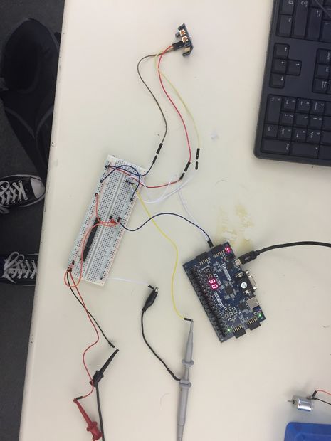
This FPGA is wired up to both an infrared motion sensor as well as an LED. When motion is detected, the sensor can send out a “high” signal to the Basys 3. At this point, the external LED is turned on and a counter is activated and stays on until the sensor is no longer sending the signal. The value for how much power is consumed during the duration of the signal is calculated and displayed.
This project includes the schematic for how to configure it, as well as all the files you need to do this in Vivado. It’s a good way to get back into the swing of things for the beginning of the year!