

For those of you that have been following my last few posts on state machines, you know that I’ve been working on Pmod interfaces for FPGA as part of making the claw game. The first one I delved into was using the PmodSTEP and Basys 3 to control a stepper motor.
Here is a video of it working:
As you can see in the video, if you flip switch 1 the motor turns on or off, and if you flip switch 0 it changes the direction of the motor.
Along with writing the FPGA driver for the stepper motor I also created an Instructable so you can replicate the functionality in the video.
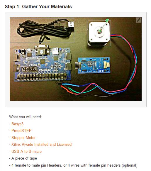
In the Instructable, I cover what you need.
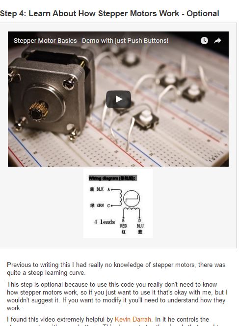
Background info on stepper motors is also available.
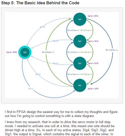
But what’s the theory behind the code?
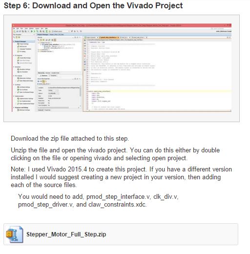
I talk about how to download, open, and program the project to the Basys3.
And lastly how to tie everything together.
To view the full Instructable, click here.
Cool project! I was just wondering, what is the difference between a stepper and brushless motor? Are there more than just those two types of motors?
please can YOU WRITE with VHDL CODE
Hi Miranda,
There are more types of motors. There are DC motors, brushless DC motors, stepper motors, and servo motors that I can think of off the top of my head.
In fact Jay wrote an instructable on different types of motors and wheels.
http://www.instructables.com/id/Motors-and-Wheels-for-Cheap-Robots/
My next tutorial will be on how to use servos with FPGA so keep watching for that. Maybe I’ll even write one on DC motors :).
There are also AC motors. The AC motors can be divided into two main types:
– synchronous motors
– asynchronous (induction) motors.
AC motors are not as easy to speed control as DC motors. Motor speed can be controlled by varying the voltage and frequency of the applied waveform (V/f control) or by wrapping a speed loop around a torque loop incorporating Field Oriented Control (FOC).
I shared on twitter:
https://twitter.com/MikoSk/status/696186202685366272
and on facebook:
https://www.facebook.com/mi.sz.90/posts/446540362211879
I like the state machine diagram, it explains what the FPGA should do. A signal diagram showing how the coils need to be driven would make it even more understandable. And some more words about how the the actual FPGA code works would also be nice (in the code I find, apart from all the temporary files, just three Verilog modules, but do not see how they are wired together…)
Hi Hendrik,
If you open the project in Vivado you will see that the top module is pmod_step_interface.v. Within that file the other two files are instantiated and the connections are shown.
If you open those three .v files in a text editor I describe exactly the connections and where they go in comments. Comments are the text after the “//”. I did this in the code because it’s hard to explain without having the code right there.
Give that a read and let me know what you think.
Kaitlyn
Hi KAITLYN,
I loved the project, I am a beginner on Verilog as I used only VHDL, could you please explain how to increase the speed of the motor?
Hey M ARIF,
You should post your question on forum.blog.digilentinc.com. There’s a whole community of people there who would be happy to help answer your questions as you get started in Verilog.
Kaitlyn