

The Analog-to-Digital Converter (ADC) is today’s go-to device for changing an analog signal into a digital binary value. The ADC takes a snapshot in time that approximates the actual value of a measured signal’s voltage. The ADC’s resolution determines how close it can approximate the analog value as a binary number. The higher the resolution, the closer it can come to the actual value.
The ADC’s binary number can be converted to a digital value if you know the ADC’s voltage range. For instance, an ADC with 12-bit resolution and a 0 – 10 volt range will have a bit value of 10 ÷ 4096 (212 ), which is 2.44 mV. This value can convert the ADC’s binary value to a digital word. Binary 1101 1100 1111 converts to decimal 3535. Multiplied by 2.44mV produces a decimal number of 8.62 volts. This is an overly simple example of figuring out the digital word value. In reality, the ADC specification sheet will list sources of inaccuracy, such as linearity, missing codes, and noise. A data acquisition device built around an ADC will also have analog circuitry before the ADC to condition the input. These components are imperfect and will further degrade the ability of the ADC to approximate the value. Always check the data acquisition device specification for true accuracy and noise.
There are many types of ADC, however, our devices typically use one of three types. The successive approximation converter, the sigma-delta converter, and the flash converter. There are other converter types, but these three tend to dominate. Successive approximation offers a good mix of speed and accuracy, sigma-delta tends to be used for slower high-accuracy applications, and flash is used mainly for speed. Pricewise, sigma-delta costs less than successive approximation types, but flash is usually the most expensive. There are other factors to consider too. For example, when designing a 24-bit sigma-delta system, you typically use more costly amplifiers and parts to achieve greater accuracy.
The Successive Approximation ADC consists of a sample-hold (S/H), a comparator, an N-bit digital-to-analog converter (DAC), a voltage reference (Vref), an N-bit register, and control logic that makes up the successive approximation register (SAR).
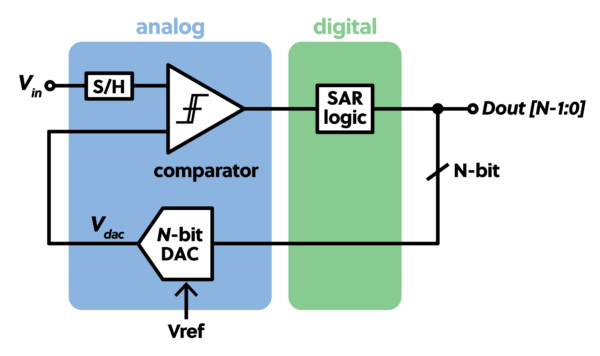
This converter type is often referred to by its acronym SAR, and the binary search algorithm best describes the functionality. The input signal is compared against N test values, where N is the resolution of the ADC. For instance, an 8-bit ADC will do eight compare operations to produce a value closest to the input.
The process begins with a start conversion signal placing the sample-hold circuit into the hold position and resetting the holding register and control logic. The sample-hold circuit must hold the input value for N clock cycles with minimum drooping. Ideally, the droop should be less than one count or the converter’s least significant bit (LSB).
The reference voltage sets the SAR input voltage range and the range of the N-bit DAC. It starts with the N-bit DAC setting its value to half the voltage range – the most significant bit (MSB) set. The value is compared to the input signal, and the result is kept in the SAR that controls the DAC. If the input value is greater, the MSB remains set. The SAR sets the next MSB on the DAC on the next clock cycle. If the input value is lower than the DAC value, the bit is set back to zero, and the next MSB is set, and so on. The comparator creates a series of ones and zeros and, one by one, shifts into a register over the N conversion cycles. Ultimately, a digital value representing the input value is made available to the outside world, usually indicated by an end-of-conversion signal. The value will never be exact because the comparator cannot determine equals. This is why the SAR ADC always has a minimum of ±1 LSB error. The Measurement Computing USB-1608G, USB-1808, and USB-1208/1408/1608-FS devices, among others, use SAR converters. These are general-purpose measuring devices best used with sensors that output greater than 0.5 volts up to 10 volts. They can also measure 4-20 mA sensors by adding an external 250-ohm resistor to convert the current to voltage.
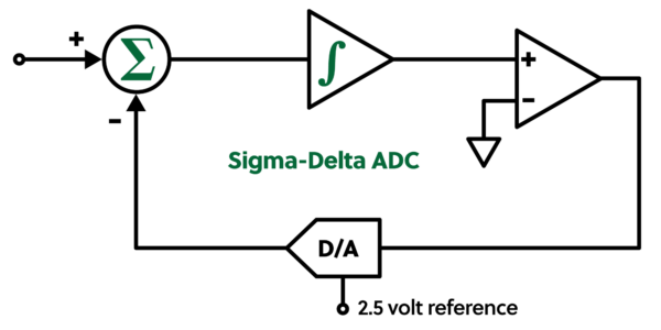
Sigma-Delta converters are less expensive and boast high sensitivity and accuracy. These are less expensive primarily because they use a single-bit DAC instead of an N-bit DAC. As shown above, the DAC value is subtracted from the input value, and the result is integrated or added to the previous. A comparator determines if the integrator value is greater or less than zero; one or zero results are created depending on the outcome. The process typically takes place millions of times a second. The string of ones and zeros created by the process is fed into digital logic that further averages the measurements to improve accuracy. The averaging behaves like a low-pass filter to remove noise and produce smooth data. Besides averaging, digital filter algorithms are typically employed to optimize noise reduction and remove 50/60 Hz noise. Below is a chart showing several conversion cycles.
| Input (volts) | DAC
(volts) |
Subtraction | Subtraction result | integrator | Comparator output |
| 1 | 0 | 1 – 0 | 1 | 1 | 1 |
| 1 | 2.5 | 1-2.5 | -1.5 | -0.5 | 0 |
| 1 | -2.5 | 1 – (- 2.5) | 3.5 | 3.0 | 1 |
| 1 | 2.5 | 1 – 2.5 | -1.5 | 1.5 | 1 |
| 1 | 2.5 | 1 – 2.5 | -1.5 | 0 | 1 |
| 1 | 2.5 | 1 – 2.15 | -1.5 | -1.5 | 0 |
| 1 | -2.5 | 1 – (- 2.5) | 3.5 | 2.0 | 1 |
| 1 | 2.5 | 1 – 2.5 | -1.5 | 0.5 | 1 |
| 1 | 2.5 | 1 – 2.5 | -1.5 | -1.0 | 0 |
| 1 | -2.5 | 1 – (-2.5) | 3.5 | 2.5 | 1 |
| 1 | 2.5 | 1 – 2.5 | -1.5 | 1.0 | 1 |
| 1 | 2.5 | 1 – 2.5 | -1.5 | -0.5 | 0 |
| 1 | -2.5 | 1 – (-2.5) | 3.5 | 3.0 | 1 |
After 13 cycles, the results show nine of the 13 bits are ‘1’ or 69% of 13 bits are ‘1’. The input range is ±2.5, which is a 5-volt span. 69% of 5 = 3.45 – 2.5, so the result is 0.95. If we were to continue, the percentage of bits would approach 70% or a result of 1.0 volts, which is our input value.
Sigma-Delta converters are often the go-to converter when measuring small and large signals. Because they boast 24-bit resolution, small signals like the one produced by a thermocouple can be resolved with reasonable accuracy, and because of the filter are mostly noise free. Large signals, too, are an application. It is not unheard of for a Sigma-Delta converter to measure signals up to ±60 volts or more. In this case, they are used for a greater dynamic range instead of small signal accuracy. Sigma-Delta devices can have input ranges in the millivolts and in the 10s of volts. You can find them in equipment that measures temperature, force, strain, load, and others. The Measurement Computing USB-2416, USB-2408, USB-TC, USB-TEMP, and others use Sigma-delta converters.
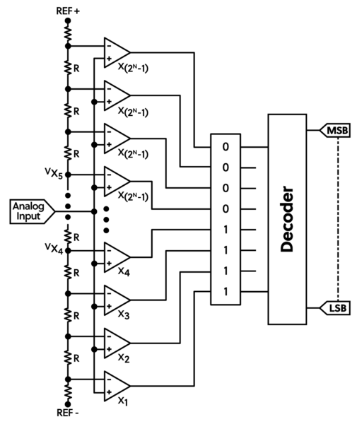
The two previous converters used a single comparator to produce a digital value over a series of iterations. It took a series of steps for the process to complete. For instance, the N-bit SAR to N clock cycles to generate the value. The flash ADC instead uses N-Comparators to deliver the value at once. Each comparator is set to switch at a specific analog value. Comparators are fast, and the conversion from analog to digital can take place at 100’s of millions of samples per second (M S/s). The Digilent Zmod Scope 1410-125 is a 2-channel oscilloscope module that employs a 14-bit flash converter and boasts samples rates as high as 1125M S/s.
Because each comparator must be laser trimmed for accuracy, the Flash converter tends to be expensive. Because of this, flash converters also tend to be 14 bits or less.
In conclusion, Analog-to-Digital Converters (ADCs) play a crucial role in modern data acquisition systems by converting analog signals into digital values. The resolution of an ADC determines its ability to approximate the analog value, and factors such as linearity, missing codes, and noise can impact its accuracy. Different types of ADCs are available, including successive approximation, sigma-delta, and flash converters, each with its advantages and applications. While successive approximation balances speed and accuracy, sigma-delta converters are cost-effective and offer high sensitivity and accuracy. Despite their differences, ADCs are essential in many measurement and control systems, providing reliable and accurate digital data for various applications. When selecting an ADC, it’s critical to consider factors such as resolution, accuracy, and noise, as well as the specific requirements of the measurement or control system. With that, you now have a better understanding of the role and tradeoffs of ADCs!
Dear John Rys,
A few years ago I was sent a link to download drivers for the Wavebook 512H.
I would like to get a link to download these drivers again, because there have been so many changes from vendors that the link you sent me years ago no longer works.
Thank you very much for taking the trouble to send this link again.
Rien Wise
Hi Rien!
We are happy to help you with that, just head over to the Digilent Forum! https://forum.digilent.com/