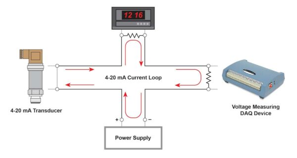
The 4-20 mA current loop interface came about because of the need to transmit information over long distances. System designers found that instead of a changing a voltage signal [that is susceptible to noise and voltage drops along the wires]they could transmit a changing current with little downside. For the most part, the information is simply a measurement or a value to control something. For instance, a factory process may need to transmit a pressure value up to the control room that is hundreds of feet away. Likewise, the control room my need to adjust the pressure by sending back a 4-20 mA signal to the pressure controller that is also hundreds of feet away.
Instruments that monitor the current level use a resistor to convert the current to voltage. The most common value is a 250-ohm precision resistor for a 1 to 5 VDC voltage drop. Ideally, a resistor for such purpose should have a 0.1% tolerance (or better) with a minimum power rating of 0.25 W and a temperature coefficient of at least 25 ppm/°C. Lower values of resistance, for example, 62.5 ohm [for a lower voltage drop within the loop of 0.25 to 1.25 VDC] will require that the instrument can adequately measure a value this low. For instance, an instrument that has a fixed 5 volt input will produce the best accuracy using the 250 ohm resistor because the voltage span consume most of the range.

Ohms Law: Current times resistance equals voltage.
Power the Loop:
4-20 mA transducers typically specify an excitation voltage of between 9 and 30 volts. The excitation voltage must be greater than the sum of all the voltage drops in the loop – including voltage drops along the wires. If for example there are two monitoring processes, the voltage needs to be greater than 10 volts, otherwise error will occur at the upper range. Instead choose a power supply that has a greater value, 18 to 24 volts seems to be popular.
It’s best to use a differentially ended input across the resistor but single-ended can also be use if care is taken to avoid ground loops. In the picture below, if the power supply negative is the system ground and the DAQ and meter are isolated then single-ended will work. However, if the DAQ device is not isolated it will get its ground from the computer and there may be a voltage difference between it and the power supply negative. In this case it’s best to use a differential connection. If there is a large difference between the negative and the computer ground it’s best to use a DAQ device that has isolation.

Also care should be taken as to where in the loop the measurement is made. If the DAQ input is sensitive to common mode voltage then put it as close to ground as possible. Elsewhere in the loop the inputs will have 5 or more volts of common mode. Isolated inputs work best in this case.
If you have any questions or if you would like any further information, the Digilent Forum is here to help!


Feels like a missed opportunity to have published this on April 20th