

A pattern generator is used to generate a user defined pattern of digital logic high/low signals or pulses. With the Analog Discovery 2‘s 16 digital channels (32 channels for the Electronics Explorer Board), you have multiple options for generating whatever digital pattern you choose, from a single signal to a full 32-bit bus.
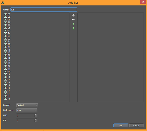
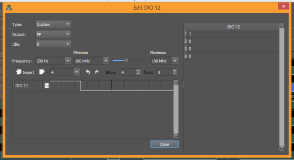
Defining the pattern on each channel couldn’t be simpler. There are a number of preset patterns you can use, like a Johnson counter or a constant value. You can also custom define each channel with a user-defined pattern.
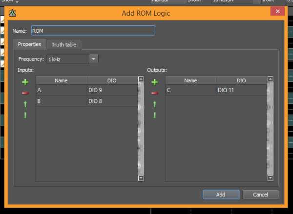
You can also define a logic truth table and use the digital channels as the inputs or outputs for said table. Simply map the input/output pins using the property tab…
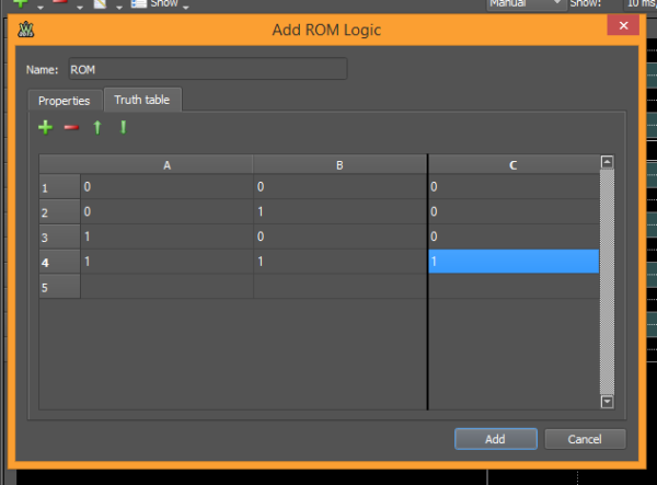
…and then define the truth table under the truth table tab.
For a more complete tutorial, check out my Instructable.
I have the EE Board and I’m having issues with Patterns. I’m trying to generate a digital pattern using 8 DIO lines (24 thru 31). I want each line to be PushPull, so that I get a steady alternating sequence of 0’s and 1’s on each line, at whatever frequency I wish to select for each line.
Here’s my problem: Even when trying to set up one line, it seems that I’m not getting a stable, steady PushPull output like you’d expect for a clock signal. The output is shifting ‘back and forth’, as it were, as viewed on a scope (I’ve tried the Digilent virtual scope as well as another literal scope). It’s as if there’s a pattern to the shifting, as if the generator is outputting a good sequence of square waves, then resetting itself and outputting another sequence of good square waves. I need a steady sequence that doesn’t do any periodic shifting.
I’m not using any trigger inputs – rather just using it in free-running mode, as type Clock, output type PP.
Once I can solve this problem on the first line, I’d like to replicate it for the other 7 lines, except each one will be running at its own frequency. But, I’d also like to have all the lines sync’ed to line 1 as a clock line. Is this doable?
What am I doing wrong?
I would post this exact question at forum.blog.digilentinc.com and you should have a response from a moderator (or another concerned citizen) shortly!