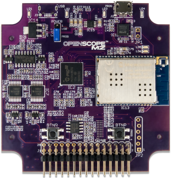
Recently, I have been trying to make some example VI’s to show people how they can connect to their OpenScope MZ through LabVIEW. The OpenScope MZ is an extremely versatile device, and at its current price point of only 89 dollars you get a lot of bang for your buck. This along with its Wi-Fi communication abilities allow it to be a great product for makers, hobbyists, engineers, and new learners. And all of these things also make it a great device for LabVIEW. People new to LabVIEW will find that it’s a great tool for getting used to LabVIEW’s user interface, while experienced users will enjoy all the added functionality that LabVIEW provides. In this post, we will be walking you through some example VIs that I made. These examples allow you to access the Oscilloscope and Wavegen/DC power supply functions of the OpenScope as well as the GPIO pins and the Logic Analyzer.
OpenScope MZ Communication Protocol
Before I talk about my examples I am going to explain how LabVIEW communicates with the OpenScope MZ. This page is a reference for the OpenScopes communication protocols. All commands are JSON objects (start with ‘{‘ and with ‘}’ or OSJB (in chunk notation) Add JSON command that went sent via terminal puts the device into JSON command mode. Below is an example command that you would use to reset the device.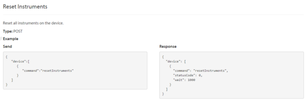
The Send box on the left contains the code that you will be sending to the device while the Response box contains the expected response. To send this command from LabVIEW, you will use the HTTP POST VI that can be found in the HTTP Client Palette. You can see an example of this VI in the picture below.
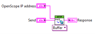
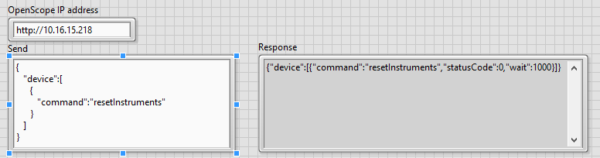
This LabVIEW VI has you input the OpenScopes URL (http:// followed by it’s IP address) and the JSON command that you want to say. It then outputs a response. The picture below shows the response I received after sending the Reset Instrument command that I show above.
LabVIEW Examples
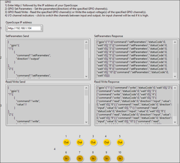
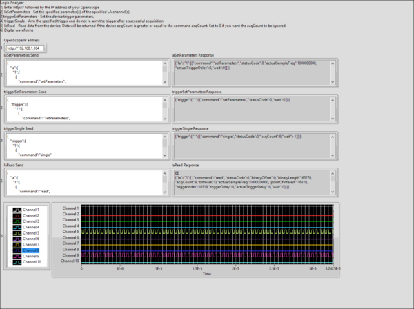
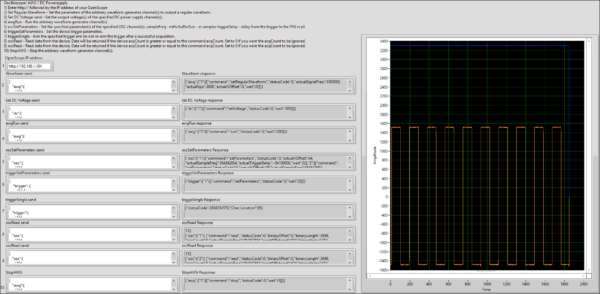
Now that you have a basic understanding of how to communicate with the OpenScope from LabVIEW we will walk through each of the three example VI’s.