

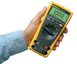
Using a data acquisition device (DAQ) can be challenging. Often, connecting to a single channel produces a suitable measurement. Yet, DAQs seldom have a single channel; trouble usually happens when two or more channels are used. When the results are unexpected, a digital multimeter (DMM), such as the Fluke 77, can verify a sensor’s output. A DMM is your go-to device for troubleshooting a system. What is frustrating is when the DMM displays correct results, but the DAQ does not. When this happens, the first thought is a defective device. This article will discuss a few areas that cause the most grief when using multi-channel DAQs.
Get to Know Your DAQ
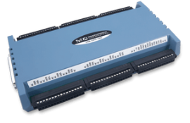
Does your DAQ have simultaneous inputs with an individual analog-to-digital converter (ADC) per channel? Or is it a high-channel-count multiplex system where one ADC is shared among many channels? This may sound overly intuitive for some, but often, the person who selected the device is someone other than the one tasked with using it. Why is this important? Because the inputs will behave differently depending on the design. DAQs with simultaneous input are easier to use than multiplexed devices but are more expensive. Devices with simultaneous inputs, like the USB-1808X or USB-1608FS-Plus, use an individual ADC for each channel. Often, these ADCs are contained in a single IC chip but can be separate ADC chips, too. For instance, the MCC 172 and WebDAQ 504 use separate IC chips for each channel.
To streamline your setup and optimize data collection, consider using DAQLog software to configure your DAQ system and manage the measurement process efficiently.
What is Multiplexing in DAQs?
DAQs that Multiplex DAQs, like the USB-2416, use ICs called multiplex switching (MUX) chips. Instead of a mechanical relay, they use a combination of solid-state analog switches to gate each channel one at a time to a single ADC chip, otherwise known as Time Domain Multiplexing (TDM). This method saves a great deal of expense but has drawbacks.
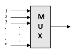
The analog switches inside the chip lack the electrical isolation of a mechanical relay. Some amount of capacitance forms between each channel when the chip is manufactured. This capacitance is a short circuit to AC signals and is an open circuit to DC. It is essential to know that when the system switches from one channel to the next, the voltage difference from one channel to the next presents itself as an AC signal and can pass through to the next channel. This is most obvious when a channel is connected to a signal while the adjacent channel is unconnected. When the system reads both, the second channel will have an image of the first, usually with less voltage amplitude.
The remedy for this is to ensure all the channels are connected to a low-impedance source (less than 100 ohms) or the system ground for unused channels. With a low-impedance source, the charge transferred to the adjacent channel instantly dissipates through the low impedance, leaving the remaining time for the channel to charge to the correct value. Unless the DAQ has simultaneous inputs, resistor dividers that reduce large signals should be avoided because they are a high-impedance circuit.
Sometimes, you can get away with using resistor dividers. They work with simultaneous inputs but not with multiplexed inputs. The reason lies in how the multiplexed inputs are sampled. Some devices scan the channels rapidly, with a minimum time between each channel. Measurement Computing’s term for when the channels are scanned as quickly as possible is Burst Mode. It is a pseudo-simultaneous mode because it keeps the time between each channel to a minimum. Take, for example, a multiplexed device rated at 100 kHz (samples per second) maximum rate. With Burst Mode enabled, two channels are sampled 10 microseconds apart (1 / 100 kHz) even though the sample rate might be slow. When using resistor dividers, you will want to avoid Burst Mode and instead opt for more time between channels. With Burst Mode disabled, sampling at 100 Hz will result in 10 mS (1/100) time between each channel. The extra time will help resistor dividers dissipate the charge transferred from the adjacent channel. Two device examples come to mind. The Measurement Computing USB-1616HS series is always enabled for burst mode, whereas the USB-1608G series can enable burst mode, making it optional.
Electrical Isolation
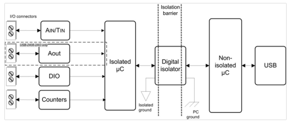
Next, know if your device is isolated. A simple way of looking at isolation is without a path to earth’s ground. For most, isolation is a sound investment, and more is better. The most common form and least expensive is device isolation. It simply isolates the device from the connected computer’s ground. This means the ground pins, which are inner connected, are floating until one is connected to a ground point, usually the sensor’s ground. An internal transformer provides additional isolation if the device uses an external power source. The other type is channel isolation, known as channel-to-channel and channel-to-ground isolation. I mentioned the trustworthy Fluke 77. It works well because it is isolated by being battery powered. Isolation prevents ground loops that distort measurements, and, in some cases, it prevents damage.
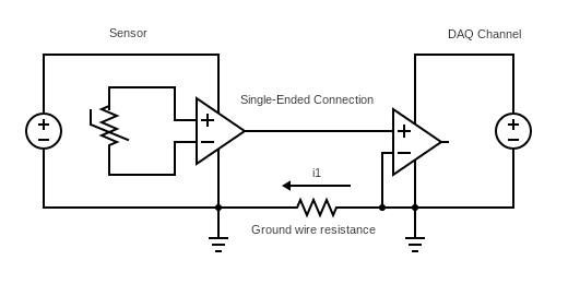
Ground Loops
A ground loop forms when there are multiple paths for current to flow to the ground. Connecting two signals, each with a connection to the ground, can cause it. The DC ground current and ground wire resistance will generate DC voltage that adds or subtracts from the sensor’s voltage. If the signal sources are close by, meaning the ground connections are nearby, there is less chance of forming a ground loop.
Thermocouple measurements are sensitive to ground loop errors because the signal measurement tends to be less than 100 millivolts. A small ground loop can change the measurement. Grounded thermocouples, which expose the wires at the sensing junction, can create a ground loop. When attached to a metal surface, the tip can make a ground loop with the next channel. This is because, internal to the DAQ, a reference resistor connects the thermocouple low side to the analog input reference. It does this automatically when the channel is put into thermocouple mode.
What do you do if you suspect a ground loop between a thermocouple and a powered sensor?
You could use a power supply whose output is isolated if practical. The sensing tip can be isolated from the metal surface using a Kapton tape that can tolerate temperatures up to 500 °F for thermocouples. For higher temperatures, you can also get mica-insulating sheets and washers designed to go between the thermocouple probe and any grounded surface. However, in some cases, multiple ground points cannot be avoided. For this application, channel-to-channel channel-to-ground isolation is the solution. The simple way to do this is to purchase an isolation module for each channel. These modules condition the input and provide isolations. There are module types for voltage sensors, such as load cells, pressure sensors, thermocouples, and more. The modules themselves output a linear voltage, so instead of using a specialized device to measure the sensor, you can use a low-cost device to measure the module’s output voltage. The 8B series modules from www.dataforth.com are the most economical, but even they will add $100-$200 per channel to the system.
Electrical Interference
As a general term, electrical interference or noise is all around us. The power grid generates plenty of 50/60 Hz noise. Electric motors, motor controllers, solenoids, relays, electric ovens, kilns, etc., generate noise; some can be filtered, but some cannot. A System that employs a Sigma-delta ADC chip is usually configured to reduce 50/60 power grid noise. When a variable frequency drive increases its speed or an electric oven ramps the temperature, the noise profile can change from low to high frequency, this non-50/60 Hz, which the digital (software) filter misses.
When encountering noise, consider nearby noise sources. Is the system located next to an electric oven or by a frequency drive that controls an electric motor? Sometimes, an obvious solution is simply repositioning the acquisition system away from the equipment. USB cables with ferrite filters also help absorb noise. When all else fails, consider the 8B isolation modules because they employ a low-pass hardware filter that will remove the noise.
Is there a simple way to test my device?
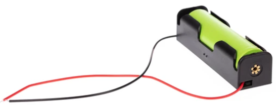
If you are experiencing troubles with your DAQ system, sometimes it is good to regain confidence by measuring a battery. It may sound simple, but a battery is an excellent low-noise, low-impedance voltage source. If the device is isolated and you are using a differential input, connect a 100k ohm resistor from the low-side input to the ADC ground.
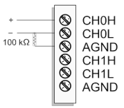
This will provide the ADC with a reference against which to measure the battery. With this newfound confidence, reconnect one of your signals. If it returns a good measurement, continue connecting signals until the problem reappears. Sometimes, only one or two creates trouble. When noise is encountered, know that the source can be a ground loop or nearby equipment. When possible, use shielded wiring like COAX or shielded twisted pair wire, but if the noise persists, it may be of the type that gets by a sigma-delta type ADC system.