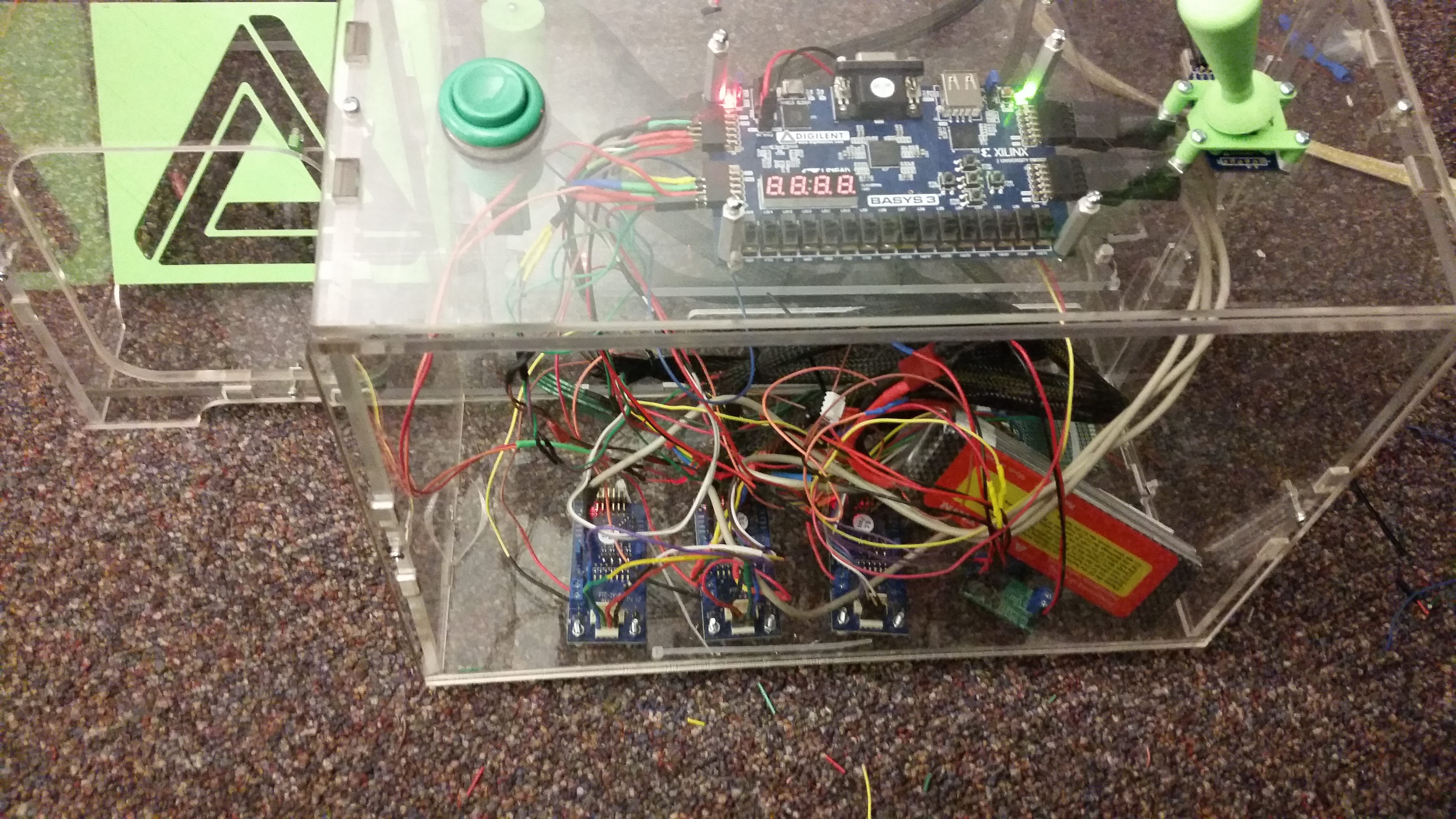
As you probably already heard, the claw game is built, programmed and ready to be shipped off to ASEE and ECEDHA. You’ve been hearing tidbits about the parts I used, including the Basys 3, PmodSTEP, and PmodJSTK. But, what you haven’t heard about is what is under the hood…what the Basys 3 is actually doing to control the movement of the claw game. Well, all of this will be revealed in good time!

However, to start with I’d like to talk about one of the most important pieces, the state machine. A while ago I wrote a post about what a state machine and state diagram is. If you’ve forgotten, feel free to check it out to get a refresher.
One reason why I like using FPGAs is because, since you are programming the hardware, everything is really flexible, deliberate, and fast. Also for being an entry level board the Basys 3 has loads of configurable I/O. If you read my post announcing the claw game was complete, then you know I used almost all of the Pmod ports.
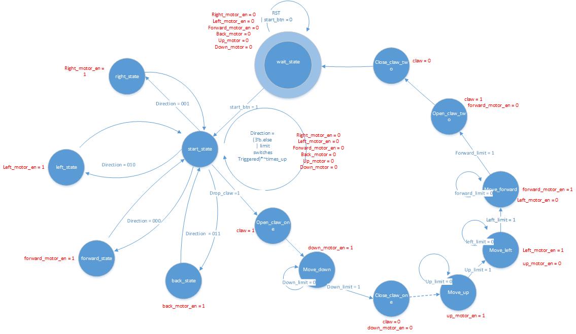
Being an FPGA, and having those characteristics as well as lots of I/O, the Basys 3 fit well to run the claw machine with a state machine. So to start I drew a state diagram. It of course changed along the way, but ended up looking something like this.

We start in the wait state, where the claw is quite literally waiting for someone to start the game. The motors cannot be engaged here, the only way to leave this state is to press the start button. Once the button is pressed it moves into the start state. Here is where the user can move the motors around to position the claw. This can be seen in the various direction states. If the joystick sends a direction signal it moves to one of those states, where it enables the corresponding motor.
Alternatively, if the drop claw button is pressed it will go into the drop claw sequence. First it opens the claw, then drops down until the down limit is reached. Then it closes the claw, to hopefully grasp a prize, then moves up and left, over the prize shoot, and opens the claw.
In the end, the drop claw button and start button ended up being the same, since they couldn’t be triggered from the same state. Now, when I said this was the final state diagram, that was a little fib. The true final state diagram includes the debouncing state, that Tommy added, to make sure the button and limit switches aren’t being triggered by bouncing. However it just makes the state diagram more complicated, and I will cover debouncing on FPGA’s in a later post. This just covers the basic functionality.

Well the diagram is fun to look at, but I’m sure you’re interested in what is actually deployed on the Basys 3, so here it is, the state machine code.
The claw machine code!
It was too long to add as a picture, and the blog doesn’t trust .v files, so a text file it is! You can view it in any text editor.
Now that you’ve seen some of the parts, and the brain of the claw machine, stayed tuned to the blog and Instructables collection for all the other pieces. After all, the brain is only one part of the battle, we still had to figure out a way to actually interface it with the Pmod ports on the Basys 3 and the outside world.


I’m glad to see the Basys 3 lives up to it’s full potential and can survive existing as the source of a childhood nightmare.
But I’m impressed you survived making the claw game– I look at “the craziness that is the electronics of the claw game” and the room starts spinning. How did you do it?