

Hi there Digilent Blog readers! I’m Dr. Brian Faulkner, professor of Electrical Engineering at Milwaukee School of Engineering in Milwaukee, Wisconsin, USA, where I teach introductory circuit theory and power systems engineering. The Analog Discovery 3 is a wallet-sized powerhouse and I’m a huge fanboy.
I’m more of a volts-and-amps guy and less of a zeroes-and-ones guy. I’ve started and abandoned at least four 7 segment display projects because I got to the digital type part and got frustrated and quit. But there’s all these digital pins on the Analog Discovery 3 that I haven’t used before so this was a fun one for me. Today we’re going to use an enormous pile of resistors to build a digital-to-analog converter from scratch and drive it with the AD3’s digital pins.
Equipment:
-
A rail-to-rail opamp
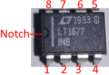
Figure 1: An op-amp
The LT1677 is the consummate generalist opamp. It’s basically got a B in every stat. It’s rail-to-rail, good input bias current, good bandwidth. It’s and everything the LM741 wishes it could be. Especially when working on the 5 volt supplies on the Analog Discovery 2/3, rail-to-rail operation is very valuable.
They’re like 5 bucks though. Don’t wire the supplies backwards and waste 5 bucks.
-
An LED
It’s a diode. It emits light. I personally like the super-bright outdoor sign LEDs from CREE but any LED will work fine.
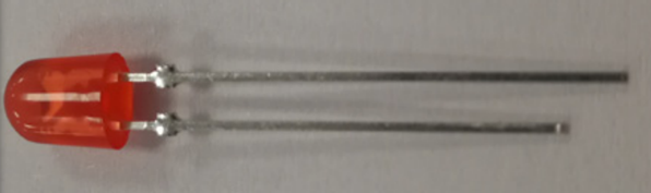
Figure 2: An LED
Any color is fine for this build, just use what you have lying around.
We’re just going to use this as a more-fun voltage detector. Higher output voltages from our analog-to-digital converter will produce brighter light.
-
An Analog Discovery 2 or Analog Discovery 3
I have enormous enthusiasm for this platform as expressed in my previous blog post. It’s just very flexible and very portable and the software is very easy to use.
Have the Waveforms software installed, plus a breadboard and jumper wires.
The Analog Discovery 3 has a ton of digital pins for doing digital stuff, we will just be using 8 of the pins and 2 of the digital functions, but there are so many more (the Protocol Analyzer is a favorite of senior design students).
If you need EVEN MORE PINS the Digital Discovery https://digilent.com/reference/test-and-measurement/digital-discovery/ has more pins, faster pins, and other digital stuff using the same Waveforms software.
None of the improved specs of the Analog Discovery 3 over the Analog Discovery 2 matter in this experiment. I will be showing the 3 in the photos of my breadboard setup.
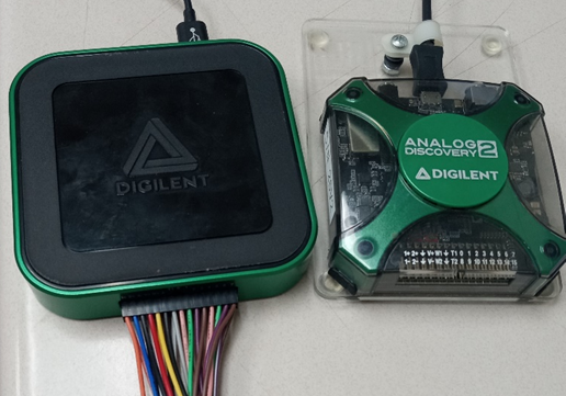
Figure 3: The back-jeans-pocket sized powerhouse
-
Thirty 10k resistors
We can’t go around pretending that resistors are exciting. They are here to support the real star of the show, the digital IO pins.
We’ll need about 30 identical 10 kiloohm resistors. Every resistor should be 10k unless you’ve got a good reason for it to be something else. It’s the most medium-est value in electronics.
The converter relies on the values being the same. One other value mixed in breaks everything.
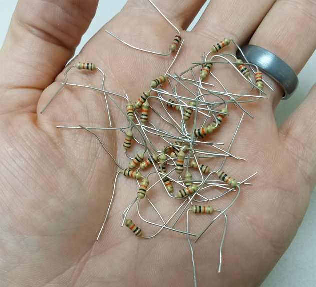
Figure 4: A handful of 10k resistors (brown-black-orange-gold) from the parts bin. Two resistors that aren’t are mixed in among them.
Guide
A quick primer on digital to analog conversion
Any digital circuit eventually needs to interact with the mechanical universe: there is no such thing as 001011 foot-pounds of torque! A Digital-to-Analog converter (DAC) converts a string of digital values from a digital system into a proportional analog voltage that can be used to drive loads that create motion, light, sound, etc. See the conversions in Table 1: the values are evenly spaced ascending by about 206 mV from one level to the next.
Table 1 Primer on 4-bit digital numbers on a 3.3V logic system
| Number | Digital String | Analog Voltage (3 digits) |
| Zero | 0000 | 0.0 V |
| One | 0001 | 206 mV |
| Two | 0010 | 413 mV |
| Three | 0011 | 619 mV |
| Four | 0100 | 825 mV |
| Five | 0101 | 1.03 V |
| Six | 0110 | 1.24 V |
| Seven | 0111 | 1.44 V |
| Eight | 1000 | 1.65 V |
| Nine | 1001 | 1.86 V |
| Ten | 1010 | 2.06 V |
| Eleven | 1011 | 2.27 V |
| Twelve | 1100 | 2.48 V |
| Thirteen | 1101 | 2.68 V |
| Fourteen | 1110 | 2.89 V |
| Fifteen | 1111 | 3.09 V |
| Sixteen | Nope not enough bits! | You don’t ever get 3.3 V! |
1. Wire up a four-bit DAC
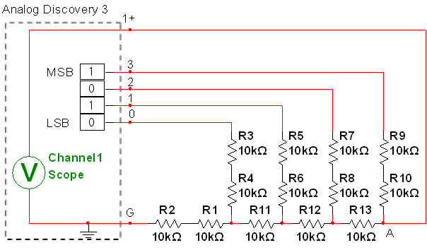
Figure 5: A four-bit converter
- Wire the circuit in Figure 5. I recommend using ribbons of wire for the digital pin connections to keep the digital part as tidy as possible.
- Double check your wiring: one resistor out of place breaks everything!
- Click Welcome->Static IO to launch the manual digital interface as shown in Figure 6.
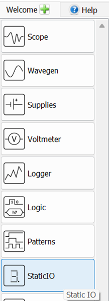
Figure 6: Opening the static IO (manual digital control) interface
- For digital pins 0, 1, 2 and 3, set them to switch->push/pull as shown in Figure 7.
Figure 7: Setting static IO pins to Push/Pull mode
- If you are ANALOG4LIFE like me, you may find it helpful to think of the digital pins as double-pole switches with one pole to a logic HIGH voltage source (3.3 V by default) and one pole to ground as depicted in Figure 8, but this depiction is not compact enough to make the schematics readable.
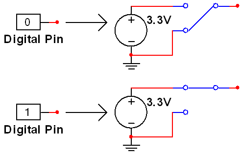
Figure 8: Digital pins in push/pull mode act like double-pole switches
- Also launch the voltmeter by clicking welcome-> Voltmeter as shown in Figure 9.
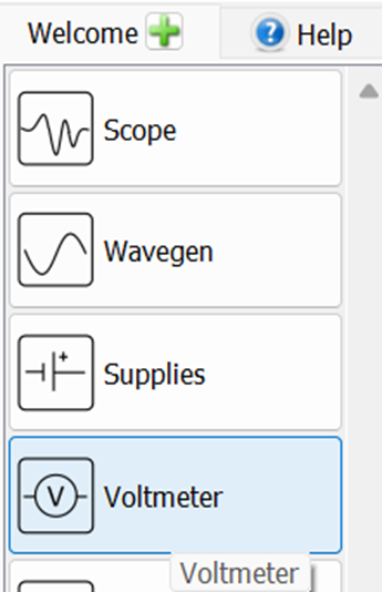
Figure 9: Launching voltmeter
- Click the “Docking windows” button as shown in Figure 10 to view both instruments at the same time.
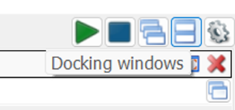
Figure 10: Docking windows is helpful for this part
- Toggle only switch DIO 3 (The most significant bit) to a 1, this bit combination (1000) is the number eight, which should have half of 3.3 volts, or 1.65 V as shown in Figure 11.
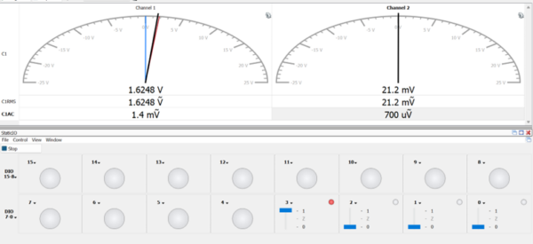
Figure 11: The analog voltage of 1.63 V quite close to the desired 1.65 V for the “Eight” (1000) level
- Play around with the button combinations and reproduce the values in Table 1, such as Fifteen shown in Figure 12.
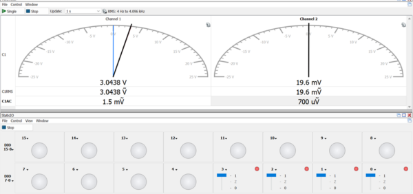
Figure 12: Fifteen (1111) is pretty close to the desired 3.09 V, an error of only 50 mV, less than a quarter of the least significant bit (206mV)
2. Look at the transients and converter performance
Clicking values by hand is insightful but takes forever. We cannot test high frequencies this way.
- Close the voltmeter and Static IO instruments.
- Click Welcome-> Patterns as shown in Figure 13.
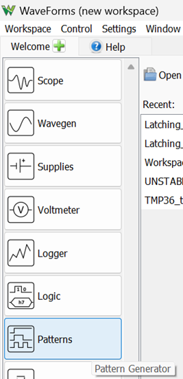
Figure 13: Opening the Pattern Generator. It basically pushes buttons super-fast.
- Click (+)->Bus to create a bus of digital pins that are controlled together as a group as shown in Figure 14.
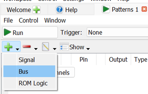
Figure 14: Creating a digital bus
- CTRL+Click DIO 0, DIO 1, DIO 2, and DIO 3 and click Insert and then Add as shown in Figure 15. Leave all the fields as the default values and Waveforms just does what we wanted anyway.
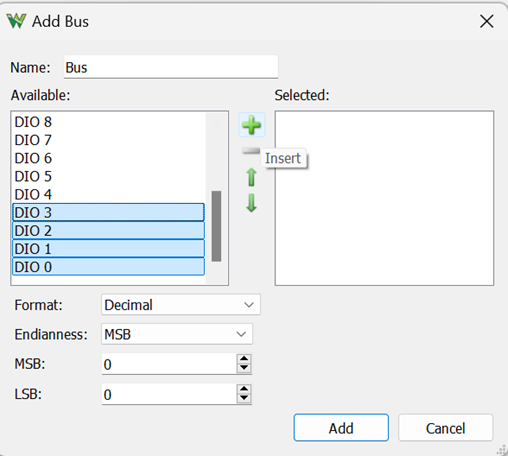
Figure 15: Grouping digital pins into a bus
- In the pattern generator, click Type-> Binary Counter as shown in Figure 16. This should automatically set the output to PP (push/pull, double pole switch mode that is either 3.3 V or 0 V). You will see a group of square pulses of different frequencies to the right as shown in Figure 16. Leave the frequency Parameter1 at the default value of 1 kHz.
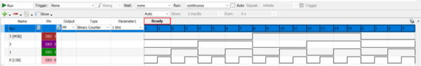
Figure 16: the generated pattern
- Click Run to start the pattern generator.
- To observe the analog output, we need an analog instrument. Open the oscilloscope by clicking Welcome->Scope as shown in Figure 17.
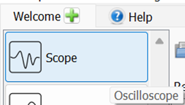
Figure 17: Launching the scope
- Click Run to start the scope capture. It will jostle all over the place, because the staircase waveform of a binary counter doesn’t have any rising zero crossings.
- Set the trigger to the falling edge at 1 V as shown in Figure 18. This should stabilize the waveform.
![]()
Figure 18: Setting the trigger. The default values work great for sine waves but must be set manually for trickier waveforms.
- Add a cursor by clicking the Y button in the upper right hand corner. The top of the staircase should measure about 3.09 V, the Fifteen level for a 3.3 V system as shown in Figure 19. It might be off by the thickness of the cursor.
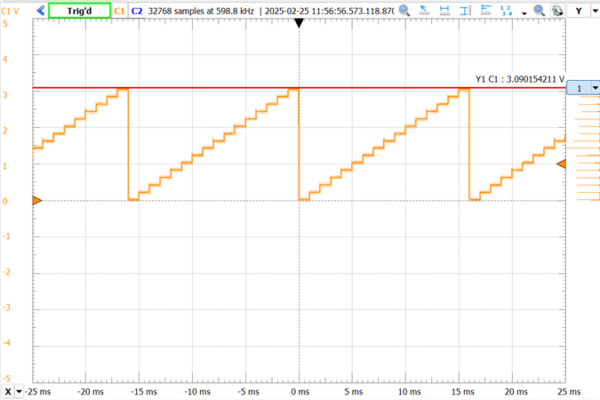
Figure 19: A DAC staircase waveform
- Increase the frequency in the Pattern Generator to 10 kHz, you should see a waveform like Figure 20. At this scale, we can see the finite settling times of about a hundred microseconds for each bit transition. The shape of the settling edge is most severe at the falling edge when transitioning from the highest state (Fifteen 1111) to the lowest state (Zero 0000).
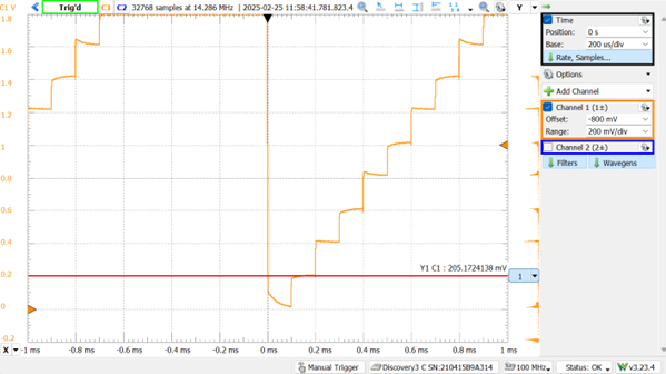
Figure 20: settling times at 10 kHz
- Increase the frequency in the Pattern Generator again to 100 kHz. At this frequency and timescale, the finite rise time of a couple of microseconds can be clearly observed as shown in Figure 21. This rise time comes from a combination of parasitic capacitances in the scope and breadboard, a hundred pF or so.
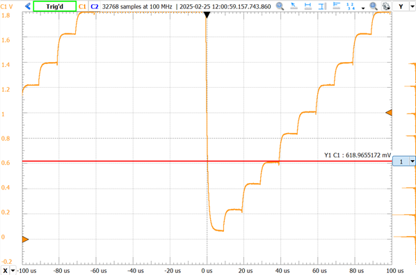
Figure 21: Stairstep waveform at100 kHz for 4-bit converter
3. Go to eight bits and an amplifier to run a load
Digital pins are wimpy, they only offer about 4 mA of output current. We’ll add an opamp that will have no trouble driving a load up to about 25 mA.
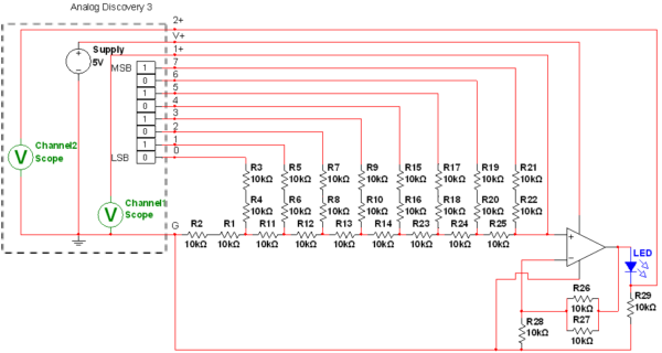
Figure 22: An 8 bit R2R ladder DAC. Yes that’s twenty nine 10k resistors.
- Wire the circuit in Figure 22. Be very patient with yourself. Keep your wiring as tidy as possible like that shown in Figure 23.

Figure 23: An 8-bit converter with an op-amp and LED load
- Click Welcome->Supplies and set the positive DC supply to Master Enable On and 5 V as shown in Figure 24.
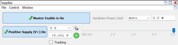
Figure 24: Enabling the DC supply for the op-amp
- The non-inverting op-amp has a gain of 1.5, which will boost the 3.29 V from the highest converter output 4.93 V, just a hair under the supply voltage. Good thing the LT1677 is rail-to-rail!
- If you’re using a 741 or other not-rail-to-rail amp, just replace the noninverting amp with a buffer. It’ll be fine.
- In the Pattern Generator, delete the old bus and create a new one with digital pins 0 through 7 as shown in Figure 25.
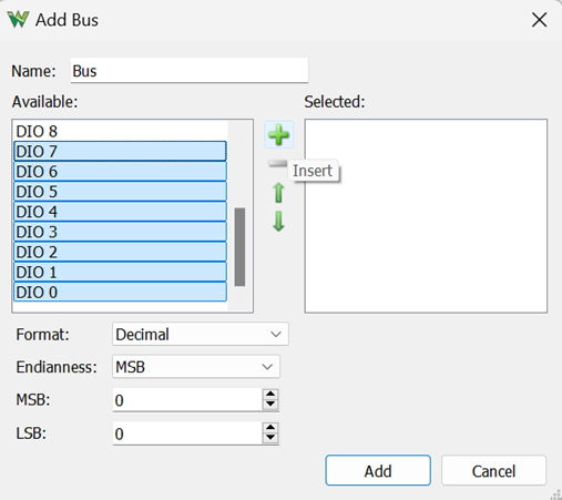
Figure 25: creating an 8-bit bus
- Set the type to binary counter again as shown in Figure 26, and set the frequency to 64 Hz, which will produce a two-second cycle length to go through all the binary values, which is slow enough to track with the human eye.
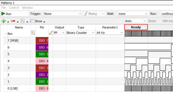
Figure 26: A 64 Hz 8 bit binary counter pattern
- Click Run to start it and go back to the scope. Change the scope mode to Screen and the scale to 1s/div. You may see a jagged, irregular waveform like Figure 27. These sudden drops in the fine staircase waveform shouldn’t be here. This converter is not properly converting binary strings to analog voltages. Something is wrong!
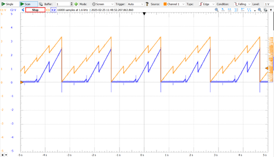
Figure 27: 64 Hz DAC output with improper behavior
- The light from the LED will rise and fall irregularly as shown in Video 1.
Video 1: R2R ladder with improper behavior causing erratic LED brightness changes
4. One of the resistors is wrong!
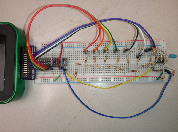
Figure 28: I spy with my little eye…
I spy resistors, most ten thousand ohms
What other things make this circuit their home?
Four ground connections, nine colors of wire
And an operational amplifier
I spy a diode emitting blue light
Eight digital pins, I count one full byte
Having all the same ohms is what matters
When you are building R two R ladders
In this entire resistor array,
Do you spy the one that isn’t ten kay?
The solution is at the end of the post, if you can’t find the mistake.
5. Run the fixed 8-bit converter
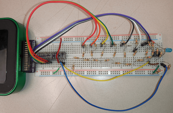
Figure 29: Brown-black-orange-gold Brown-black-orange-gold Brown-black-orange-gold…
- Find and replace any wrong-value resistors in the circuit to remove the errors.
- Debug the op-amp part too (check that it has power and negative feedback).
- When any glitches are fixed, you should see a triangle-shaped wave again on Channel 1. This triangle wave is actually a very, very fine staircase waveform with 256 steps.
- Channel 2 monitors the current through the LED using the series resistor R29. After the output reaches the turn-on voltage of the blue LED, it begins tracking linearly as shown in Figure 30.
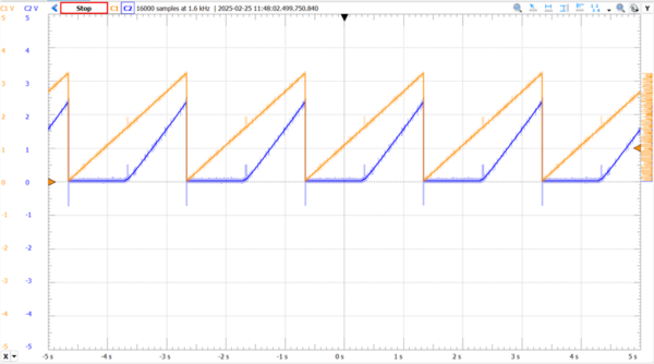
Figure 30: 64Hz with pesky glitches fixed
- Since LED brightness is proportional to current, the brightness of the LED tracks with the level of channel 2 as shown in Video 2.
Video 2: Properly working DAC circuit driving a blue LED
Wrap-up
Well that was fun! We learned a bit about how to pilot the digital features and the issues that lie on the border between the Kingdom of Analog and the Empire of Digital. This can give you a little insight into the experimental issues that DACs can have. The R2R ladder is not the only DAC, but it’s one of the easier ones to build on a breadboard from boring passives and amplifiers.
Oh, you didn’t want to mess with that? Digilent even sells a little R2R ladder module in Figure 31 that all the resistors are definitely the right value! https://digilent.com/shop/pmod-r2r-resistor-ladder-d-a-converter/
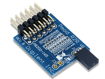
Figure 31: In the words of chef Ina Garten, “If you don’t have homemade, store bought is fine”
To the professors in the audience: I’ve rewritten all my circuit labs here at MSOE all around the Analog Discovery 2. All 30ish of them are compatible with the new Analog Discovery 3 and feature at least one sensor or transducer. If you are looking for circuits lab experiments that don’t put your students to sleep, drop me an email ([email protected]). Taking circuit theory isn’t the price of admission to interesting subjects like controls and instrumentation, it can be fun on its own, and it should be fun.
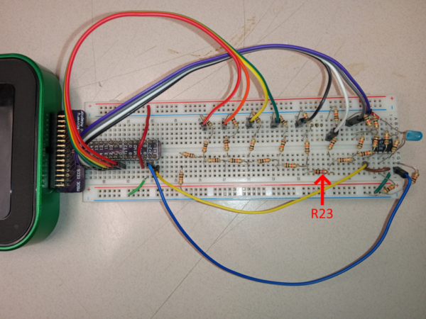
Figure 32: It was R23 that was brown-black-RED-gold instead of brown-black-ORANGE-gold. And that blew up everything.
I used the MCP6004 op amp in my electronic-design class. It only costs 59¢ for a rail-to-rail op amp that is fine for low frequencies and low-voltage power supplies.
Thanks for the part recommendation! We were using the LT1677 in both intro circuits and electronics, the higher specs mostly needed for the junior year course. 59 cents is a great rate. I rarely have reason to go over 200kHz, so low frequency is not really a restriction.
P.S. I quite like your book!