

This blog post goes over one of several new features we’re announcing as part of the WaveForms 3.21 release.
New Feature: Scope to Digital
We’re introducing the “Scope to Digital” feature, which allows you to interpret captured analog signals as digital signals when using the Scope instrument’s Digital view. The Scope to Digital feature is supported by all of Digilent’s WaveForms-compatible Test and Measurement devices, from the original Analog Discovery through to the Analog Discovery Pro 5000-series and Eclypse Z7.
Stepping back a second, if you haven’t seen the Digital view before, check out the image below. This is an extra pane that can be added into the Scope instrument. It allows you to use the digital and analog inputs next to each other on the same screen, with the same triggers. Changes to time base and position are applied to both charts, so whenever you zoom in on a particularly interesting region of a signal, you don’t need to fiddle around to get everything to line up correctly.
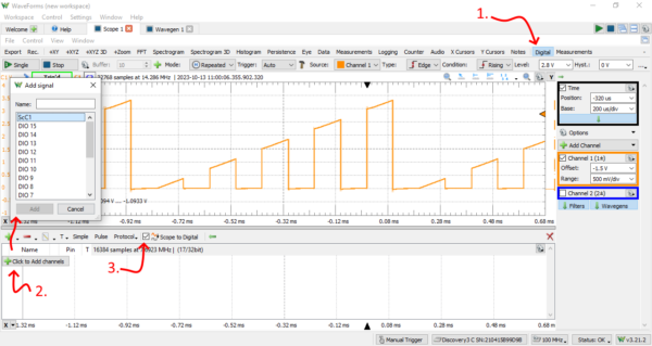
In the image above, we can see: (1) The button to enable the Digital view, which takes up the bottom half of the window. (2) The dialog to add channels to the Digital view, in this case, “Signal” was selected to add only a single-bit signal to the plot. And (3), the checkbox to enable Scope to Digital.
What Else Can the Digital View Do?
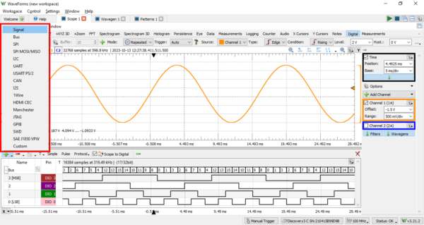
What else can the Digital view do? It implements many of the same features as the Logic Analyzer, integrating them in with the Scope instrument. All familiar types of signals are supported – single-bit signals, buses, SPI, I2C, and UART interfaces, in addition to many other standard and custom protocols. All the familiar digital trigger functionality, including pulse triggers and protocol triggers (like triggering on ), from the Logic Analyzer instrument is supported for true digital inputs. When a digital trigger is used, the analog inputs are automatically set up to trigger at the same time.
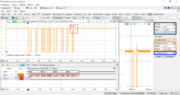
Here, we can see a UART line being decoded with Scope to Digital. An additional synchronized pulse is used to keep the trigger stable.
What is Scope to Digital?
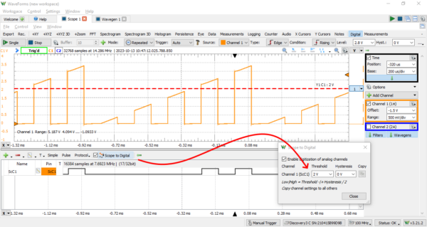
so, what is Scope to Digital? When enabled, WaveForms application will digitize all enabled analog inputs in software and allow them to be added to the Digital view. This is why we are allowed to select “ScC1”, Scope Channel 1, in the Add signal dialog.
There’s more to it, threshold voltages used to digitize the signals are configurable – meaning that many different logic standards can be supported, potentially even those beyond the normal capability of your device’s digital inputs. This could include CAN signals, 15 V RS-232 signals using the UART protocol, and RS-485 signals, for a few examples. Because thresholds are individually configurable per channel, you can even mix-and-match.
See how to configure logic thresholds by following the red arrow in the image below. Click the “Scope to Digital” button, then set a threshold in the dialog. In this example, we can compare the Scope plot to the Digital plot – only the pulses that exceed the 2 V threshold are digitized as “one”s.
There’s one important caveat. Because the analog to digital conversion is implemented in software, digitized analog inputs cannot be used for digital triggering. That said, you can always still pass the same signal to both a digital input and an analog input simultaneously as long as that signal is compatible with both of those inputs. Software digitization removes the hassle of wiring up two inputs in situations where you have other trigger sources.
With all that, check out this short clip, showing the previous example in motion. As the threshold voltage used to digitize Scope Channel 1 is lowered, more and more pulses appear in the Digital view.
Try it Yourself!
You can download the latest version and check out Scope to Digital today, by navigating to the WaveForms Resource Center.
WaveForms 3.21.2 adds a couple other new features. Check out some more posts describing them, here: Analog Input Filters – Reducing Noise in Acquired Analog Signals, Extent for Measurements. For a full list of changes, check out the change log on our Reference site: WaveForms 3.21.2 Changelog.
Useful feature and blog post explaining it, thank you. I’ve used this functionality in Picoscope 6 & 7 and figured I must not know how with Waveforms & AD3, but now I know why I couldn’t find it. Being able to characterize the quality of the physical layer of e.g. CAN signal ( protocol that I need it for ) while looking at frame data has been useful to me. I don’t understand the limitation of no “digital triggering” as I see several CAN trigger options when I select CAN in protocol drop-down of Digital view including ability to trigger on data of CAN frame.
Yes, scope to digital channels can’t be used as trigger sources. We appreciate the question and have passed your comment on to the development team for WaveForms to see if this can be made more clear in the user interface.