Check out a video of the project on the Digilent Instagram!
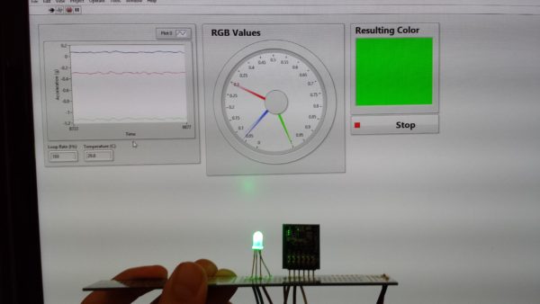
With the new LINX 3.0 release, I thought it would be a cool idea to do a project with the Raspberry Pi 2 and LabVIEW! This project uses a Raspberry Pi 2, a PmodACL2, an RGB LED, a Digilent PCB Ruler, and LabVIEW MakerHub LINX in order to change the color of the LED depending on the acceleration measured. The front panel is also updated to reflect the measurements of the red, green, and blue colors as well as the expected LED color!
If you want to make this project yourself, check out the Instructable and see this Instructable for info on how to setup your Raspberry Pi or BeagleBone Black. If you haven’t seen LINX in action, check out the LabVIEW MakerHub LINX 3.0 intro video below!
If you’re a maker and you’re interested in using LabVIEW, Digilent sells a Raspberry Pi and LabVIEW Home Bundle together called the Raspberry Pi 2 Physical Computing Kit.
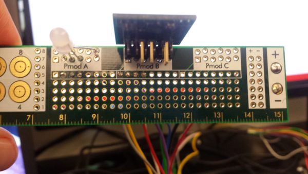
The first step for this project (and most time consuming step, in my opinion), is to start soldering. Because we’re connecting the RGB LED and the PmodACL2 to the Raspberry Pi, we’ll need wires from the PCB ruler connected on to the Raspberry Pi 2. These wires allow the Raspberry Pi 2 to get the acceleration values from the PmodACL2 and update the colors of the RGB LED on the ruler. We’ll need to solder 3.3V and ground on the right side of the ruler, and we’ll also need 3 wires for the RGB LED and 4 wires for the SPI communication with the PmodACL2.

Each of the RGB legs corresponds to a different color, and the fourth and longest leg is the common anode for the LED. When you drive one of the color legs low, that color will light up. You can also mix colors by turning on multiple colors at once.

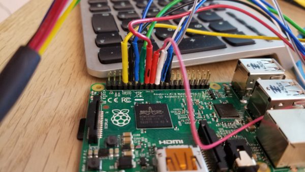
Once all the wires are soldered, we connect the wires to the Raspberry Pi! Check out the LINX pinout here for the board. Chip select of the Pmod (the first pin) is connected to pin 7 on the Raspberry Pi. Ground is to pin 9, LED blue to pin 11, LED green to pin 13, LED red to pin 15, power to pin 17, MOSI to pin 19, MISO to pin 21, and SCK to pin 23. The connections should all be in one row like it is pictured above.
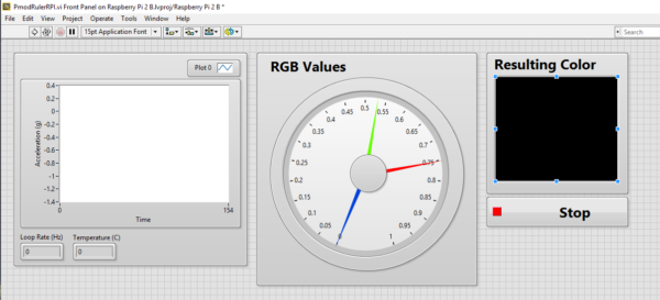
Here’s what the LabVIEW front panel looks like:

And here is our block diagram:
 The LabVIEW code opens a reference to the LINX device and the PmodACL2. The PmodACL2 is set to record a scale of ±2g with CS on pin 7, SPI channel 0, and a output data rate of 100Hz. Next we enter a while loop. For each loop, we read the acceleration values from each axis and display them in a chart on the front panel. We then take the absolute value of the acceleration values and compare each axis acceleration value to 0.4g. If the acceleration is less than 0.4, the corresponding axis color is written high (this is because the LED color turns on when we drive the leg low not high!). When the acceleration is above 0.4g, the corresponding LED color is written low and the color turns on. To display our resulting color on the front panel, we use a select block to determine if each color is on or off (there’s no PWM on the RPI so it’s all on or all off).Then we write the RGB colors and combine them to give the expected color from the RGB led on an indicator on the front panel. Once the while loop is ended, we write all the RGB legs high to turn off the RGB LED and then close the PmodACL2 and LINX references.

One way to improve this project would be to add PWM instead of just turning a color all the way on or all the way off. This would allow for even more color combinations! In the LabVIEW code, you could take a percentage of 1g as the PWM value and then you could take this percent of 255 to get the corresponding RGB values to display the color on the front panel!


2 Comments on “Raspberry Pi Rainbow Ruler”