

Hi there Digilent Blog readers! I’m Dr. Brian Faulkner, professor of Electrical Engineering at Milwaukee School of Engineering in Milwaukee, Wisconsin, USA, where I teach introductory circuit theory and power systems engineering. The Analog Discovery 3 is a wallet-sized powerhouse and I’m a huge fanboy. This experiment is about a tactile exploration of the torque, speed, voltage, and current of electrical machines. I had learned “torque is a constant time current, speed is a constant times voltage” on the blackboard before, but the kinesthetic understanding you get from feeling torque and speed with your own hands is so much better. And the Analog Discovery 3 gives us the perfect platform to explore this phenomenon.
Equipment:
Geared PMDC Machine
A geared brushed permanent magnet DC motor is the star of our show today. These are the same ones you can get from simple robotics kits. You need one with gearing, so that human-producible speeds can result in significant voltages.
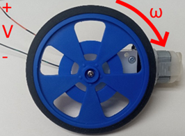
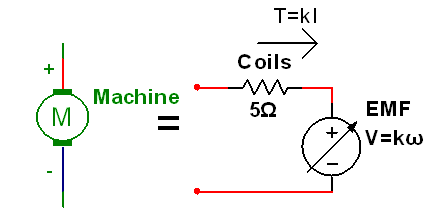
Figure 1: PMDC machine physical hardware, schematic symbol, and model
- Brushed permanent magnet machines can act as a motor or as generator.
- Faster spinning = more volts. Direction of rotation changes polarity of voltage
- Stronger turning = more amps. Direction of current determines direction of torque.
A Supercapacitor
Unlike regular capacitors, which are firmly in the “boring passives” category, supercapacitors are interesting because they can store enough energy to interact with electro-mechanical devices. They’re like 2$ on Digikey right now. Have some fun and buy a few. Their stored energy and output current are high enough to weld your jumpers together if you aren’t careful.

Figure 2: Supercapacitor capacitor photo and schematic symbol
- Supercapacitors are polarized. The extra electrons MUST go on the (-) side indicated by the stripe on the side. Reverse polarity will electrochemically damage the capacitor.
- Supercapacitors have very large capacitance, so large currents for a long time are required to bring them up to full operating voltage.
- I’m using 1 farad, but a half farad would still work. One millifarad will NOT store enough energy to be impressive. You need a proper supercapacitor.
An LED
It’s a diode. It emits light. I personally like the super-bright outdoor sign LEDs from CREE but any LED will work fine
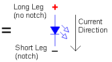
Figure 3: An LED
- I’m using red, but any color is fine.
- We’re just going to use this as a more-fun voltage detector. When the generator makes enough voltage to turn the LED on, it will glow, but it requires very little current so it doesn’t disturb the rest of things by very much.
Some resistors
Resistors are boring passives, but reliably so. You always know exactly the nothing that they will do.
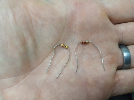
Figure 4: Resistors. Yup they’re resistors all right. That’s pretty much it.
- The little 10 ohm will be used as a current sense resistor for time-varying currents.
- The 330 will protect the LED from overvoltage by limiting current.
- The currents we’re working with are modest, ¼ watt through-hole resistors work fine.
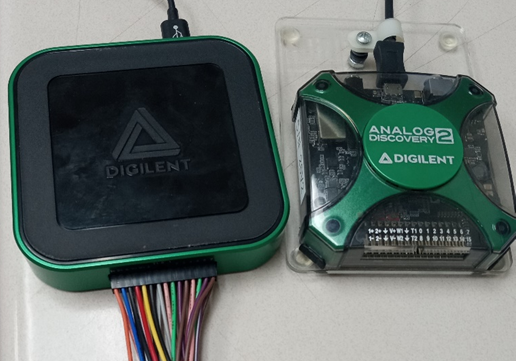
An Analog Discovery 3 or Analog Discovery 2
I have enormous enthusiasm for this platform as expressed in my previous blog post https://digilent.com/blog/ignite-a-neon-lamp-using-the-analog-discovery-3/ . It’s just very flexible and very portable.
- Have the Waveforms software installed, plus a breadboard and jumper wires.
- We will only be using the oscilloscope function on low voltages today, none of the power supply functions.
- None of the improved specs of the Analog Discovery 3 over the Analog Discovery 2 matter in this experiment. I will be showing the 3 in the photos of my breadboard setup.
Guide
1. Spin faster to get more volts
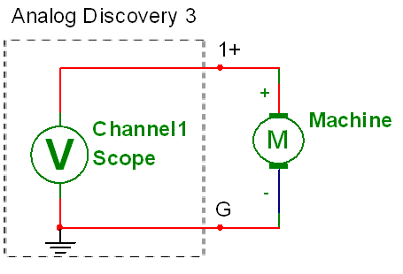
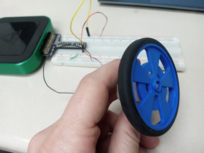
Figure 6: Open circuit voltage measurement
- Connect channel 1 of the oscilloscope to the machine as shown in Figure 6 and connect the other end to ground.
- Click Mode->screen to set the oscilloscope to live rolling display mode. Set the time base to 1 s/div. This is a slow, human-reaction time scale experiment.
- Hold the machine so that you can comfortably rotate the shaft wheel. Rotate the drive shaft with your fingers. You should measure a voltage on the scope like that in Figure 7.
- Speed up to about one cycle per second. This should produce a positive DC voltage of about 6 V, with a lot of AC ripple riding on it as shown in Figure 7 and Video 1. This ripple is due to the commutator brushes inside the machine. The Analog Discovery 3 has hardware filtering for noise, but we don’t need that for this experiment.
- The voltage measured should be positive. If the measured voltage is negative, swap the leads of the machine so that the comfortable spin direction will produce positive voltage.
- Make note qualitatively of how hard the shaft is to spin. This is the friction torque with no electrical load.
.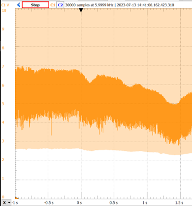
Figure 7 :Typical generating voltage waveform with no load
Video 1: Spin faster, get more volts
2. You are the prime mover – You are the energy source
We are not using the Analog Discovery’s power supply. We are the power supply, our hands provide mechanical energy, which the machine converts into electrical energy, which the LED converts into light energy.
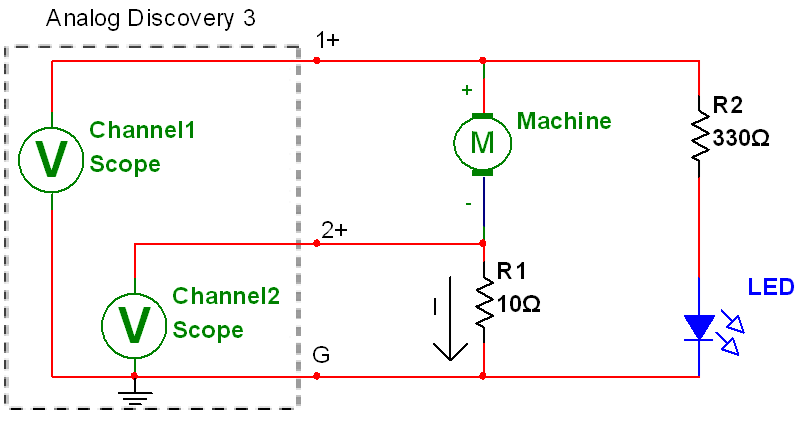
Figure 8: Driving an LED
- Add a 10 resistor, LED, and 330 to the circuit as shown in Figure 8.
- Channel 2’s connection measures time-varying current using the 10 sense resistor and labels the machine in the passive sign convention. When current is negative, the machine acts as a generator, converting mechanical energy into electrical energy. When current is positive, the machine acts as a motor.
- Spin the shaft fast enough to cause the LED to light up. The faster you spin, the higher the voltage and the brighter the light. It should feel just a little bit harder to spin than in the no load case, since the LED is a low-current load (10 – 20 mA).
- The waveform observed should resemble the one in Figure 9 and Video 2.
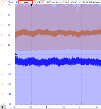
Figure 9: Current waveform driving an LED at about 10 mA
Video 2: Powering an LED with the DC machine as generator
4. Drive a short circuit
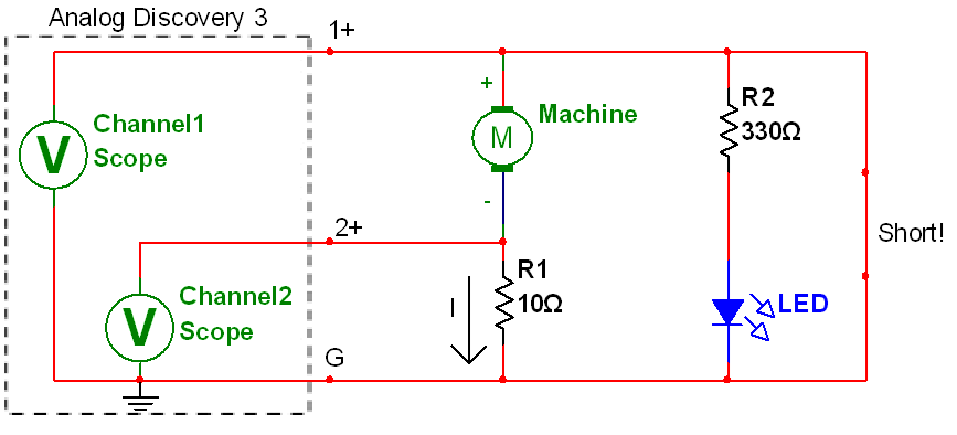
Figure 10: Short-circuit test
- Add a short-circuit jumper wire between the positive terminal and ground as shown in Figure 10.
- Spin the drive shaft. The wheel will be much harder to spin! Minimum resistance-> maximum current -> maximum torque!
- You will see a waveform like the one in Figure 11. The output voltage is (nearly) zero and the output current is much larger, hundreds of mA.
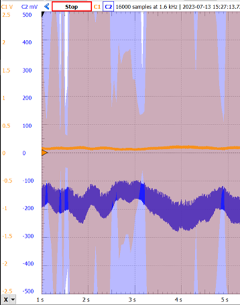
Figure 11: Short circuit current is very large compared to the LED current
5. Charge a supercapacitor with your own hands
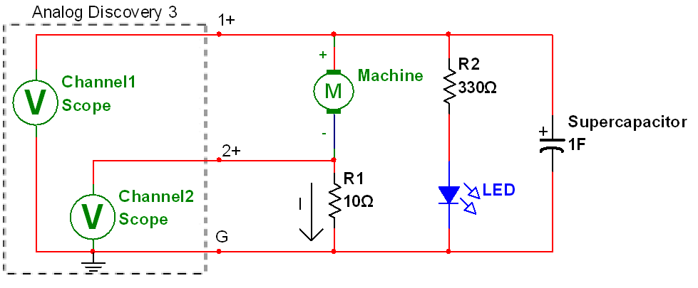
Figure 12: Charging a supercapacitor. Seriously don’t put the cap in backwards. I mean it.
- Replace the short circuit wire with the supercapacitor as shown in Figure 12.
- Double check that the (–) side of the capacitor is to ground! Don’t ruin your supercapacitor with reverse voltage.
- Spin the drive shaft. It will be difficult like the short circuit, but slowly get easier as the capacitor voltage rises. The waveform should resemble that in Figure 13.
- Continue spinning the drive shaft until the measured voltage reaches 5 V.
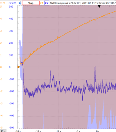
Figure 13: Capacitor charging waveform has wiggles because my hand is stronger on the downward stroke than on the upward stroke.
6. Let go of the drive shaft to operate the machine as a motor
In the previous step, the machine acted as the source, providing energy and the supercapacitor acted as the load, absorbing energy. Now they will swap roles.
- When the voltage reaches 5 V, let go of the machine’s shaft.
- The wheel will continue to spin in the same direction, but the current will swap sign! The supercapacitor is now the source, and the machine is now the load: it is now a motor, not a generator. There’s no power supply in the circuit; the supercapacitor has become the energy source now.
- Current will be nearly constant to overcome sliding friction in the motor, and capacitor voltage decreases linearly with time as shown in Figure 14 and Video 3.
- Apply a small mechanical load of friction torque to the wheel with your fingers. The machine will slow down and the current will rise slightly.
- Grab the wheel firmly and prevent the machine from rotating. The machine current will spike sharply, then decrease exponentially. This is the capacitor discharging through the copper windings of the machine.
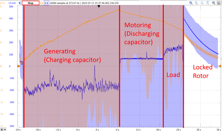
Figure 14: Negative current when generating, positive current when motoring, and then huge current under locked-rotor conditions.
Video 3: Supercapacitor transient here
- We can see the power of the machine more directly by using one of the math channel options. Click Options->Add Channel -> Custom (software) to open up a new math channel. Multiply the voltage from channel 1 with C2/10 (the current) to get the power. Set units to watts as shown in Figure 15It’s technically the total power of the machine and the sense resistor, but we’ll ignore that small difference.
- The power channel will show a trace much like Figure 16.
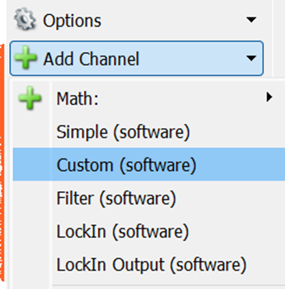
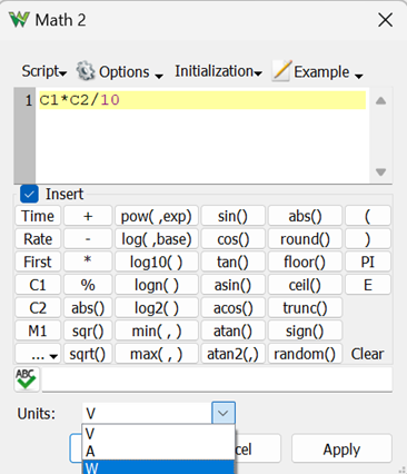
Figure 15: Adding a power channel
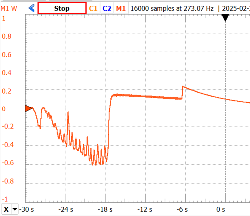
Figure 16: Power channel display directly in watts
Electromechanical energy conversion rocks
Well that was fun! I find this experiment to be the best way to really understand, in a kinesthetic way, the torque/speed/voltage/current relationship in DC machines. This experiment also makes the passive sign convention really “pop”. The fact that the same machine can act as both motor and generator is easier to believe when you feel it with your own hands.
To the professors in the audience: I’ve rewritten all my circuit labs here at MSOE all around the Analog Discovery 2. All 30ish of them are compatible with the new Analog Discovery 3 and feature at least one sensor or transducer. If you are looking for circuits lab experiments that don’t put your students to sleep, drop me an email ([email protected]). Taking circuit theory isn’t the price of admission to interesting subjects like controls and instrumentation, it can be fun on its own, and it should be fun.
I really appreciate how this experiment bridges theoretical concepts with hands-on experience. Feeling the torque change as you spin the motor and observing the LED’s response offers a tangible understanding of electromechanical principles. It’s a compelling demonstration of energy conversion in action!
It’s fascinating how a supercapacitor can replace traditional power supplies for this kind of experiment. I’m curious how the system would behave with motors of different power ratings—has anyone tested this with smaller motors?
This experiment offers a compelling look into measuring DC motor torque and speed using supercapacitor power. The approach of leveraging supercapacitors not only enhances energy efficiency but also provides a unique perspective on transient response analysis. It’s fascinating to see how integrating these components can lead to more sustainable and responsive motor systems.
I find it fascinating how the experiment leverages supercapacitors for power management in motor testing. The combination of measuring torque and speed in real-time is a valuable approach for improving the efficiency of motor-driven systems, especially in robotics.
This hands-on experiment brilliantly bridges theory and practice. Feeling the torque increase as the supercapacitor charges, then observing the motor’s behavior as it discharges, offers an intuitive grasp of electromechanical energy conversion. It’s a compelling way to internalize concepts like the passive sign convention and the dual roles of machines as generators and motors.
Super interesting experiment! It’s wild how a motor can flip roles like that. Makes understanding torque and speed way easier.
Great!!
Thanks for sharing
This whole experiment really nails how torque and speed work together—it’s super hands-on and eye-opening. Kinda reminds me, if you’re into tech stuff, check out something like this https://wan25.ai for some cool visual effects.
Great experiment! It makes the concepts of torque and speed much clearer when you can feel them.
Cool hands-on project. I love how they injected practical experience into pure theory.
Solid work showcasing how theoretical concepts can be explored with simple tools. Inspiring!
Very Good Sharing
Great hands-on way to understand motor torque and speed.
Thanks for sharing such a creative and well-documented experiment—definitely inspiring to try it myself.
Cool to see supercapacitors in action with a DC motor. It reminds me why I enjoy tinkering with electronics.
Cool experiment! The supercapacitor power source for the DC motor is a neat twist. Curious about how the AD3 handled the varying voltage during discharge for torque and speed measurements.
Thanks for sharing this hands-on experiment with the Analog Discovery 3! I love how you connected theory to real-world feel, making torque and speed concepts much clearer. It’s inspiring to see practical learning in action.
This is a great hands-on way to learn about motors using the AD3. Very helpful!
Love the supercapacitor power idea for this. Using the AD3 with a Hall effect sensor for RPM and the strain gauge for torque measurements is a fantastic setup. The Fritzing diagrams really help visualize it all!
The kinesthetic understanding point is spot on. There’s something irreplaceable about feeling the torque change as you vary current that no textbook derivation can replicate. Curious whether you found the AD3’s bandwidth limiting for faster motor transients.
I’ve always been curious about using supercapacitors for motor applications, so this was a great read. Your method for capturing the torque/speed data was really clever—I might have to try a similar setup in my own workshop. Thanks for sharing the practical details!
Interesting approach using a supercapacitor for power delivery—I’ve always wondered how the torque curve looks under such rapid discharge conditions. The AD3 setup you described made the data collection seem really straightforward. Might have to try a similar test with some spare motors I have lying around.