

Hi there Digilent Blog readers! I’m Dr. Brian Faulkner, professor of Electrical Engineering at Milwaukee School of Engineering in Milwaukee, Wisconsin, USA, where I teach introductory circuit theory and power systems engineering. The Analog Discovery 3 is a wallet-sized powerhouse and I’m a huge fanboy. We will use the 5 volt peak waveform generator to light a 90 volt neon glow lamp, all without danger of electrocution!
Equipment:
A Neon Lamp
In the awesome rock band that is analog electronics, transducers and actuators are the lead vocals. They’re the components that DO something. They accomplish what the system is built to, either to learn about the physical world or to act in the physical world.
- Neon bulbs require about 90 volts to “ignite” the gas in the tube and glow.
- After lighting, they maintain a near-constant voltage of about 60 V if the current is at least a few microamps, and when the current drops too low they go dark again.
- I find that neon lamps that require 120 V to ignite just barely don’t work, get a 90V lamp like the NE-2 1A1.


Figure 1a and 1b: Neon lamp photograph and schematic.
A Transformer
In the awesome rock band of analog electronics, we have exciting components like amplifiers, timers, and transformers on guitar. And this experiment has some pretty good solo parts for the transformer.
- I’m using a TRA1370 that I found lying round in the parts room that was donated to the school a few years back. I’m using the center tap to get the step-up ratio I want.
-You need a turns ratio of about 10:1.
-You need a core at least the size of a golf ball. Small audio transformers won’t work, their magnetizing reactance and saturation flux are too small. Every transformer I’ve ripped out of an old power supply has worked.
![]()
![]()
Figure 2a and 2b: Transformer and schematic. This transformer is center tap, I just ignore wire 3.
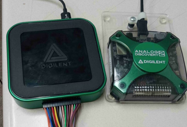
An Analog Discovery 2 or Analog Discovery 3
In the awesome rock band of analog electronics, we’ve got measurement instrumentation and power supply on drums and bass, backing up the rest of the crew and keeping time.
- Have the Waveforms software installed, plus a breadboard and jumper wires.
- The output voltage of the waveform generator is limited to 5 V peak since they run on USB. We will use a transformer to increase this maximum, as well as use two waveform generators together for an extra doubling of voltage.
- The measurement voltage range on the scope is. We will build an attenuator to measure high voltage anyway.
- The output current is limited to about 40mA. We exploit this limitation as a backup safety feature.
- None of the improved specs of the Analog Discovery 3 over the Analog Discovery 2 matter in this experiment. I will be showing the 3 in the photos of my breadboard setup.
Resistors
Ah resistors. Necessary, but boring support components. The roadies in the rock band of electronics. This experiment uses high voltage, but very low currents so ¼ watt resistors are adequate.
2x 100kΩ , 1x 10kΩ resistor, 1x 1MΩ resistor (I use 1 Meg resistors far more often than my undergraduate instructors led me to believe I would.)
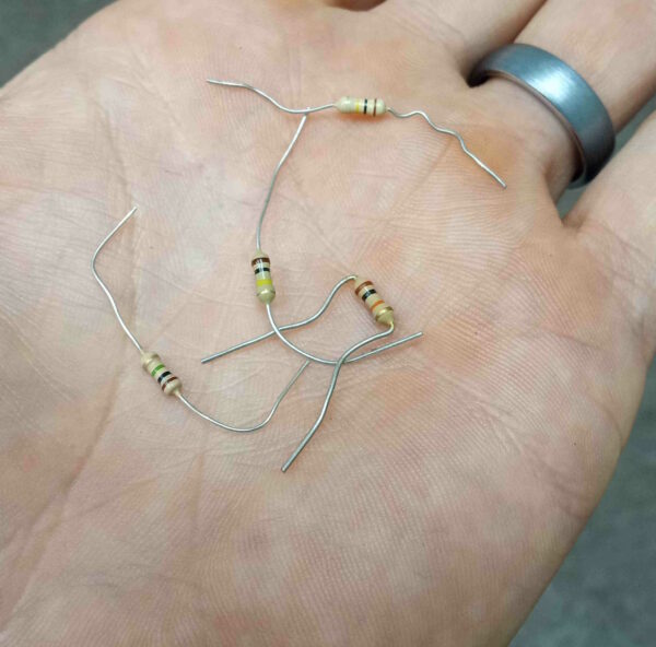
Figure 4: Resistors. They are not fun but they’re important.
Guide:
Drive the Step-up Transformer
The Analog Discovery 3 has a maximum AC output voltage of 5 Vpk, and a maximum measurement range of 25 V on the scope channels.
![]()
Figure 5: Transformer measurement circuit diagram.
![]()
Figure 6: Transformer test on the breadboard.
- Build the transformer measurement circuit shown in Figure 5. One lead on both the primary and secondary is connected to ground.
- Set the waveform generator to 2 Vpk and 1 kHz.
- You should see a 2 V sine wave on channel 1 and a much larger sine wave on channel 2 as in Figure 7. If you use the same pins I did on the transformer, the voltage is also inverted. Neon bulbs do not care about polarity so this is fine.
- Scale the V/div on channel 2 and channel 1 large enough so that the voltage step-up effect is clearly visible. I’ve got both channels of 5 V/div.
- Change the amplitude of the waveform generator so that the output is greater than 20 Vpk but less than 25 Vpk.
![]()
Figure 7: Woah nelly that’s a lot of extra volts! Step up transformers are just so much cooler than step down.
Drive Two Waveform Generators Back-to-Back
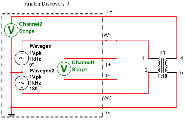
Figure 8: Bipolar AC drive circuit.
- Enable the second waveform generator channel and synchronize them as shown in Figure 9

Figure 9: Enabling second waveform generator channel.
2. Build the circuit shown in Figure 8. Pin 2 of the transformer is now driven by the second waveform generator channel and is NOT connected to ground.
3. Use the 1+ and 1- pins (differential scope) for channel 1: it measures between the two wavegen outputs. Unlike most scopes I’ve used, using the differential measurement is not a huge pain that requires checking out extra parts, it just goes and I never worry about it.
4. Set the second wavegen channel to the 1Vpk and 180 degrees out of phase. The two channels together have a maximum output of 10 Vpk working together.
5. Verify that the input voltage on channel 1 is the sum of the two waveform generator channel voltages: 2 V peak when each channel is at 1 Vpk.
6. Crank up the voltage until the output exceeds the 25V maximum measurement capability of the AD2 as shown in Figure 10.

Figure 10: 2 volts in, 25 volts out. Nearly the same waveform as before, but our maximum is now doubled.
Build an Attenuator to Measure High Voltages
The AD2 is incapable of measuring more than 25 V natively. To measure higher voltages when driving the transformer harder, we will use a resistive divider. The divider resistance (1.1MΩ ) is much higher than the internal resistance of the transformer (≈6kΩ ) to avoid loading down the transformer output.
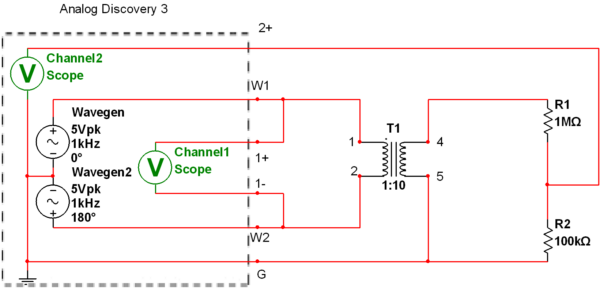
Figure 11: Transformer circuit with attenuator to measure high voltages.

Figure 12: Who knew all those voltage divider calculations we did in circuits class were good for something?
- Add the attenuator resistors R1 and R2 as shown in Figure 11.
- Connect channel 2 to measure the voltage across R2, rather than directly measuring the very large transformer output voltage. R2’s voltage is 1/11th the transformer voltage.
- Click Add Channel -> Custom
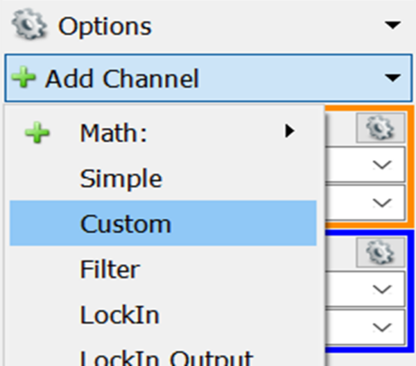
Figure 13: Adding a math channel does not require digging around in 15 menus to find
4. Program the math channel to multiply channel 2 by 11, so the display reads the actual transformer voltage as shown. The Waveforms interface is easy to use. It’s just very easy.
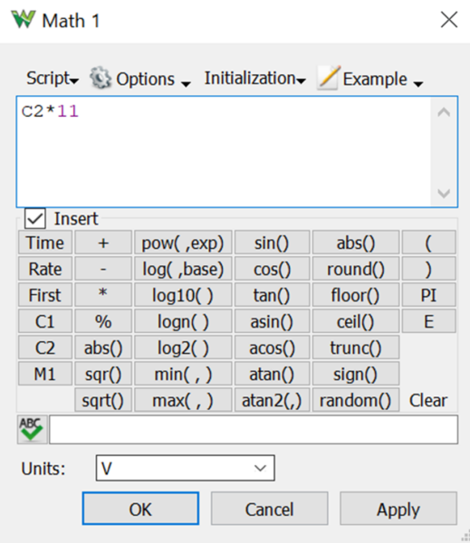
Figure 14: Programming a math channel is very easy.
5. Raise both waveform generator channels to 5 V peak to achieve maximum output voltage. The input voltage is now 10 V peak from the sum of the two waveform generators. You should have an output voltage from the transformer of about 100 V peak as shown in Figure 15. Don’t worry about polarity.
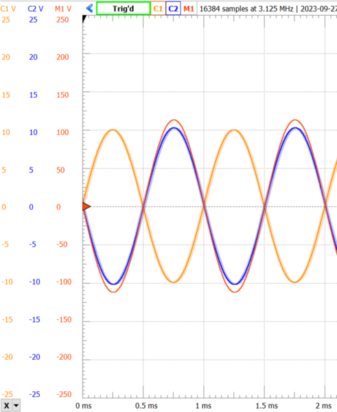
Figure 15: Input and output waveforms of dual drive, measured with attenuator.
Ignite the Neon
Neon will not turn on for less than 90 V. If it glows, that means there is real high voltage present! Misuse of the math channel or instruments cannot make neon glow.
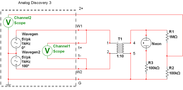
Figure 16: Neon glow bulb circuit.
- Turn off the waveform generator before making modifications.
- If you touch the high voltage output, it tingles and surprises you but the maximum output current is too low to be harmful.
- Add a neon bulb and resistor to the circuit as shown in Figure 16. The resistor protects the neon from carrying excessive current.
- The neon should begin to glow. Neon lamps are non-linear devices, so they distort sinusoidal waveforms as shown in Figure 17.
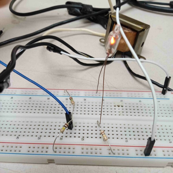
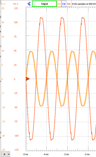
Figure 17a and 17b: Neon bulb glowing and waveform distortion.
If you see the lamp start glowing before you plug in the second leg as shown in Figure 18, you are completing the circuit through capacitive coupling. Your body is a conductor separated by the insulating air from the blue ground rail conductor. You are a capacitor. These currents are so small that they are harmless, just a few microamps. The brightness of a neon lamp is proportional to the current, as shown in the figure 18 the lamp is just barely lit. These currents are below my threshold of perception, I am unable to feel anything, but they’re there because the neon is glowing.
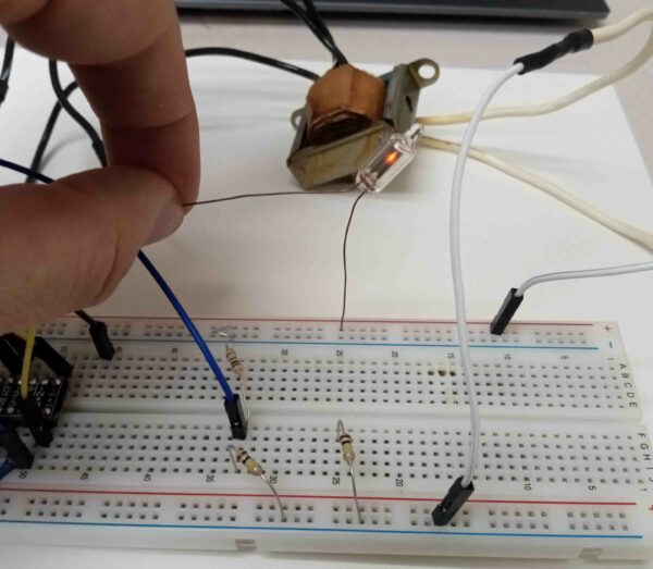
Figure 18: Capacitive coupling is spooky.
Measure the Neon Current
You want to know what the current is? Just add one more resistor. This is where I’d like to have an Analog Discovery Pro with the four voltage channels. We must give up being able to measure the input voltage to see the output current and output voltage together, but we know we have high voltage so that’s fine.

Figure 19: Measuring current. I like to use the “jump” notation for wires that cross but do not connect just to be extra clear, in addition to using a different color.
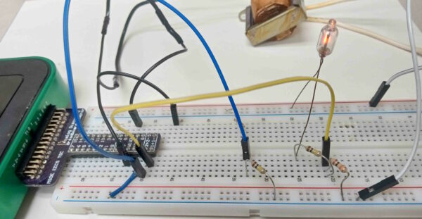
Figure 20: Measuring the neon current waveform.
- Add a 10k resistor in series with the neon to use as a current sense resistor with one end to ground, and use Channel 1 of the scope to measure its voltage as shown in Figure 19.
- Add another math channel, this time setting the mode to current. We have a 10 resistor, so divide the value by 10 thousand.
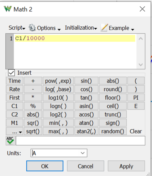
Figure 21: Making a current channel is also easy, just click the units option.
3. The little “notch” taken out of the voltage waveform occurs just as the neon begins to conduct, at around 90 V just like it should be. It continues to conduct until almost the next zero crossing.
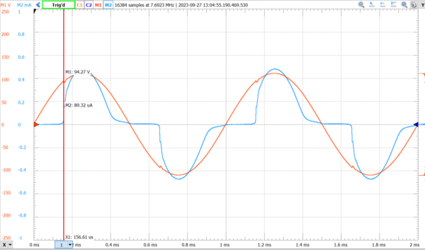
Figure 22: Current and voltage waveforms from the math channels. Peak currents are just under a half a milliamp.
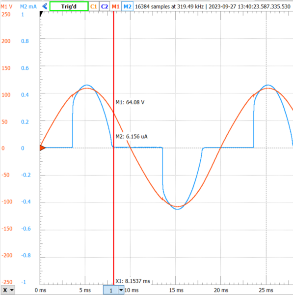
Figure 23: Waveforms at 50 Hz show the glow start and stop much more clearly.
At lower frequencies (50 Hz), the extinction of the glow at a voltage near 60 V is much more obvious, since the transient behavior of the glow and the capacitance of the neon bulb itself are less pronounced, so the waveform is much cleaner. As seen in Figure 23, the current starts very abruptly when the ignition voltage is reached, and the current stops when the glow extinguishes when the voltage falls below the minimum glow voltage.
It’s the Current (Density Through the Heart) That Kills You, Not the (No Load) Voltage
Wait one second, is it safe to ask undergraduates to use a 120 V output?
- The Analog Discovery 2’s maximum output current capability is about 40 mA. Dividing that by the turns ratio of about 1:10, the output current on the secondary could be, at most, 4 mA. This limit applies before and above any imperfections of the transformer. Touching the transformer output causes a weird, unpleasant tingling sensation, but it is not painful due to the small maximum current. See Figure 24.
- The primary low voltage winding of this transformer has resistance of about 50 ohms, and the secondary high voltage winding about 1200Ω. The total cantilever impedance reflected to the secondary side is (50Ω)10^2 + 1200Ω = 62000Ω . A human body represents a load of about 1000Ω, so the human body is exposed to a voltage of about 1/7 the terminal open-circuit voltage if touching the H winding, about 14 Vac, a nonlethal voltage commonly output by benchtop waveform generators.
- The leakage reactance of the transformer further limits current to the load of a human body.
- I did once do this experiment with a push-pull AB current amplifier on the waveform generator, giving the full 800 mA capacity of the DC supplies as AC. That one bit me painfully when I touched the secondary of the transformer. Don’t do that.
- A student with an implanted medical device vulnerable to electrical disruption (such as a pacemaker), should notify their instructor before attempting this experiment.
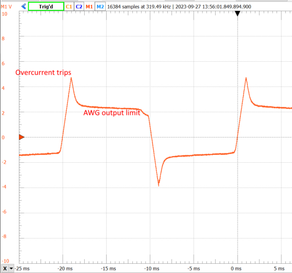
Figure 24: Output voltage waveform when loaded with a 1k resistor, similar in value to a human body’s internal tissues when the skin has broken down.
Note the AD2 overcurrent protection kicking in when the output current gets too high in Figure 24. Even without the overcurrent protection, the peak would be only about 10-15 V if you follow the trajectory of the sine wave that has been decapitated by the overcurrent protection, because the internal resistance of this transformer is rather high.
Wrap Up
Neon glowed with high voltage. We didn’t electrocute ourselves with high voltage. We didn’t destroy our measurement instruments with high voltage. Analog electronics is cool! There are so many interesting experiments that you can do. Parts are cheaper than ever, and the instrumentation is more accessible than ever too.
To the professors in the audience: I’ve rewritten all my circuit labs here at MSOE all around the Analog Discovery 2. All 30ish of them are compatible with the new Analog Discovery 3 and feature at least one sensor or transducer. If you are looking for circuits lab experiments that don’t put your students to sleep, drop me an email ([email protected]). Taking circuit theory isn’t the price of admission to interesting subjects like controls and instrumentation, it can be fun on its own, and it should be fun.
This is a really interesting lab for many reasons with a lot of takeaways such as the fact I learnt that it is current not voltage that can shock the body and as little as 20mA. I used to think that anything under 50v was safe to handle.
Although I use Analog Devices ADALM1000 which is similar to Digilent’s Analog Discovery device (without negative voltage capability) I can still follow along both in theory and practice. Thank you very much for the light and enjoyment this brings.