

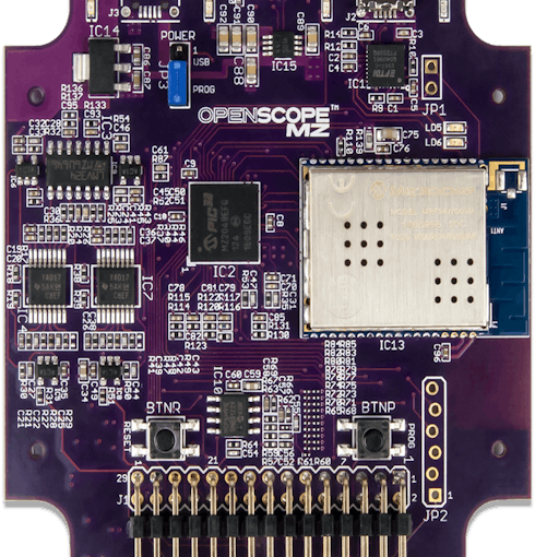
This blog post will show you how to use your OpenScope MZ to read the output of a first order RC circuit. The OpenScope MZ is an extremely versatile device, and at its current price point of only 89 dollars you get a lot of bang for your buck. This along with its Wi-Fi communication abilities allow it to be a great product for makers, hobbyists, engineers, and new learners. And all of these things also make it a great device for LabVIEW. People new to LabVIEW will find that it’s a great tool for getting used to LabVIEW’s user interface, while experienced users will enjoy all the added functionality that LabVIEW provides. This post will allow you to access the Oscilloscope and Wavegen functions of the OpenScope.
Materials Needed
All included in LabVIEW Interaction Parts Kit
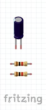
- Two 1K ohm resistors
- Take them from the small bag on your desk
- One 33 μF capacitor
- Take it from the small bag on your desk
- One small breadboard
- Wires
Setup
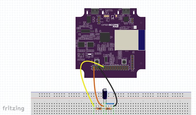
- Place the 33 μF capacitor on a breadboard, connect the solid orange (OSC1) wire from the OpenScope to the anode (the longer leg) of the capacitor.
- Next, run a 1K resistor from the cathode (the shorter leg) and a wire from the anode to a pin connected to the solid black wire (GND) of the OpenScope.
- Finally, run another 1K resistor from the cathode to a pin connected to the solid yellow wire (AWG) of the OpenScope.
Software Settings
These settings are all preset in the LabVIEW VI:
Time
- 50ms/div
Trigger
- Rising edge
- Osc Ch 1
- 100mV
Osc Ch 1
- Volts 200mV
- Offset 400mV
Wavegen
- Square wave
- Frequency 3 Hz
- Amplitude 2 Vpp
- DC Offset 1V
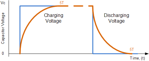
Expected Results RC Waveform
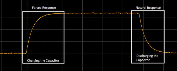
Useful wave shapes can be obtained by using RC circuits with the required time constant. The voltage drop across the capacitor alternates between charging up to Vc and discharging down to zero according to the input voltage. If we apply a continuous square wave voltage waveform to the RC circuit whose pulse width matches that exactly of the time constant of the circuit, then the voltage waveform across the capacitor would look something like this:
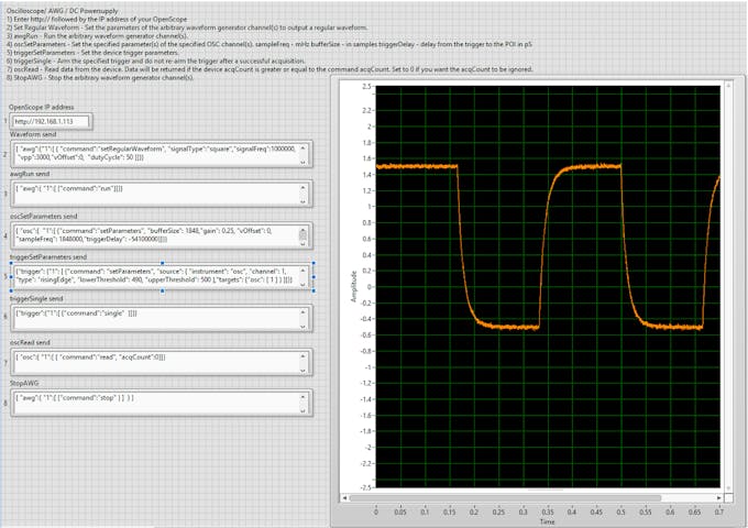
Results

If you set up the circuit correctly you should get an output similar to the one seen above. This is in line with our expectations based on the software settings I set in LabVIEW. For more theory and equations, go to Real Analog Chapter 7.
OpenScope MZ is OpenSource!
Thank you for reading the post, to learn more about using the OpenScope in LabVIEW check out this Hackster.io project. If you are interested in trying out these examples yourself but don’t have the right supplies you can purchase LabVIEW 2014 home bundle for only 50 dollars. You can also purchase the OpenScope MZ on Digilent’s website. Please comment with any questions or comments you may have.