

Recently, a new channel was added to the Oscilloscope Tool. Now in addition to the two original oscilloscope channels, the basic and custom math channels and reference channels, you can also add a filter channel.
To demonstrate this channel, first I’ll start with a custom waveform. Open the Waveform Generator and select the custom mode. Click new, to add a new custom channel.
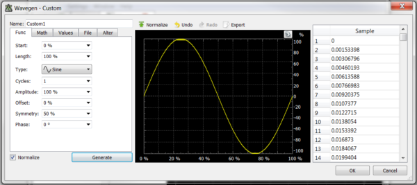
We’ll start with the default sine wave. Make sure the default settings match mine, and then click generate.
Next we’ll need to add a higher frequency component. Open the Alter tab and make sure +Add is selected. Click Alter with.
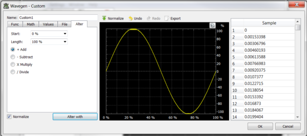
Here, the same default sine wave will populate. Change the Cycles selection from 1 to 10. This will add a sine wave component with 10 times the frequency. You should see the waveform that I have below in the Custom window. Click okay to add it to the Waveform Generator.
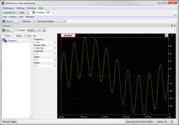
Make sure that your custom waveform that was just created is selected, then and click Run. Connect the Waveform Generator to Oscilloscope Channel 1.
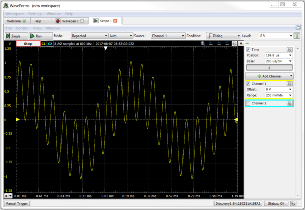
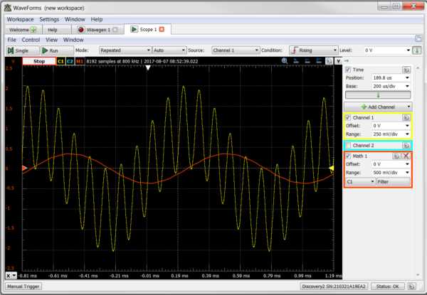
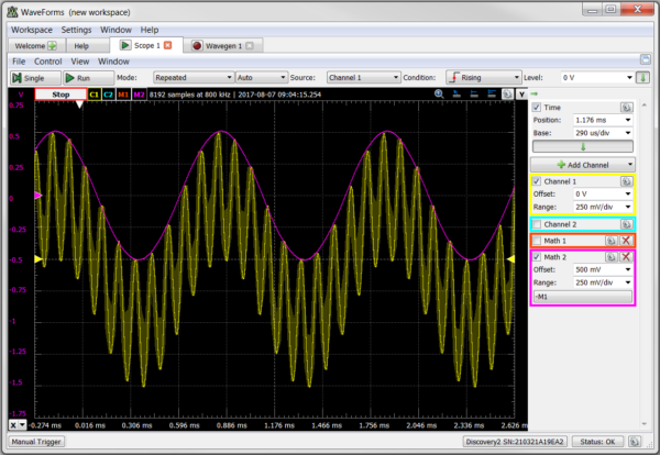
Open the Oscilloscope Tool and click run. You may need to change some of the channel and time settings to see the portion of the waveform shown above. Make sure all your settings match those in the above image.
Next we’ll add a new filter channel.
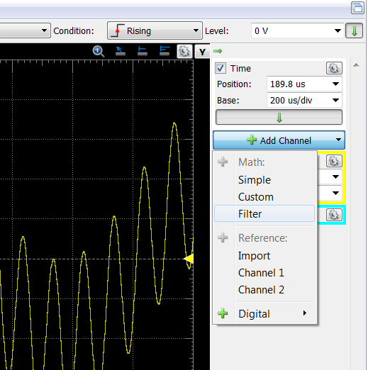
Click Add Channel, and select Filter under the Math heading.
You should see a Math Channel with Filter settings added below Channel 1 and 2.
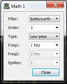
Click on the Filter Button to open the settings. Filter gives the option of a Chebychev, Butterworth, or Custom filter. When Chebychev or Butterworth are selected, you can choose between 2nd and 16th order, Low pass, High pass, Band pass, or Bandstop, and one or two cutoff frequencies. When Chebychev is selected, you can also choose the Eplison parameter. When Custom is selected, the filter is determined from the table of coefficients.
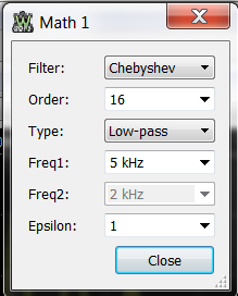
For this example, I’ll need a Chebyshev low pass filter of order 16. I’ll choose a cutoff frequency of 5kHz, since its above the lower frequency of 1kHz, but lower than the higher frequency component.
Click close and you should see the lower frequency component of the custom waveform, a 1kHz sine wave.
If you have any questions about the filter channel or the update to WaveForms, comment below or post on the Digilent Forum. If you want to learn more about filters, check out Real Analog chapters 7, 8, and 11, which cover filters.
Hi Kaitlyn,
I ordered the Discovery 2. The first impression is that theese tool is a very usefull and powerfull tool.
The first step to start different measurements are very easy! Very nice!
I have a question about digital filtering by using the script generator. My intention is to great a script with the follow function:
1.) Reading the oszi chanel 1
2.) move the signal from chanel 1 through the defined filter.
3. Take the output signal of the filter and export it to the signal generator.
Doing this in the obove defined manner I dont need an analog filter.
Thank you for your information.
Best regrads
Jürgen