

Welcome back to the Digilent Blog!
As we continue on with our exploration of the Pmods, after checking out some of the Output Pmods like the DAC, Audio, and Visual Pmods, we find ourselves at the final set (at least for now) of output Pmods. These five Pmods all drive different types of motors including servo, DC, and stepper motors. Through these Pmods, you can get your project on the move, whether its a robot arm, a box monster, or a line-following robot.
We’ll start out by checking out the PmodCON3.
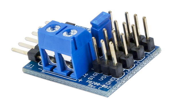
This peripheral module is designed to drive up to four servo motors. A servo motor is a type of motor that tends to be restricted in its movement between two different angles. They are also somewhat slow compared to the rest of the motor world. So why use them? Servo motors are used in any application where you need precise movement. By giving the servo motor different pulse lengths of PWM signals, a user is able to tell a servo motor to move to an exact angle within its rotation range. With the PmodCON3, it’s easy to control a robot arm without having the large mess of wires that normally comes with controlling multiple motors.
Digilent also offers two Pmods that are dedicated to driving DC motors: the PmodHB3 and the PmodHB5.
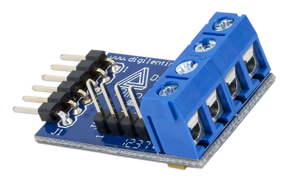
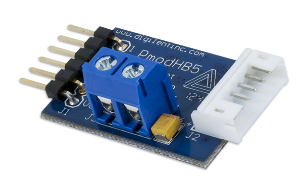
These two peripheral modules include a 2A H-Bridge circuit that is capable of handling up to 12V. An H-bridge, specifically a full H-bridge, is a type of circuit that allows a voltage to be applied across a device in two different directions. In terms of the PmodHB3 and the PmodHB5, this means that the motor that these Pmods are attached to will be able to run either forwards or backwards. Both of these H-bridge modules control the speed of their DC motors through PWM. DC motors, unlike servo motors, are able to rotate freely much, much faster, but do not have precise control over how far the motor rotates. Both of these motors also have two pins that are able to give feedback on the attached motor’s current speed and rotation.
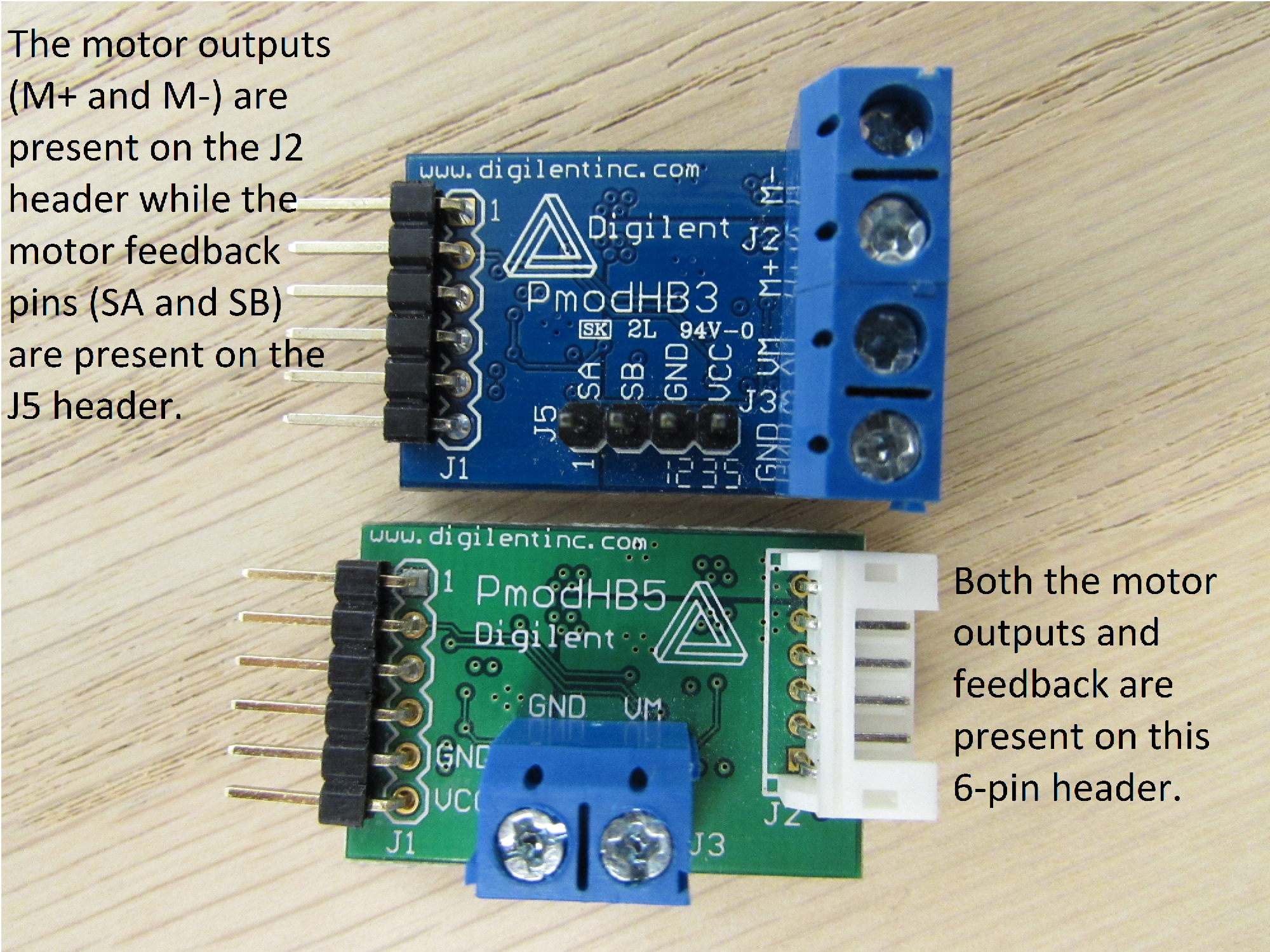
Much like the PmodCLS and PmodCLP, these two Pmods seem to not have any differences between them. Yet, the two different names necessitates that the two modules are different. The difference between the two is how they incorporate feedback from the Hall effect sensors.
A Hall effect sensor, as a broad approximation, is a type of device that adjusts its voltage output based on the magnetic field that is associated with the motor spinning. The PmodHB3 presumes that the attached motor does not inherently include Hall effect sensors and thus provides a separate header from the motor terminals to receive the voltage signals from the separately attached Hall effect sensor. On the other hand, the PmodHB5 presumes that Hall effect sensors are incorporated with the DC motor and provide their feedback signals on the same header has the incoming motor inputs from the host board.
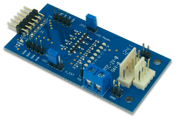
Finally, Digilent has two Pmods that are able to drive a stepper motor: the PmodDHB1 and the PmodSTEP.
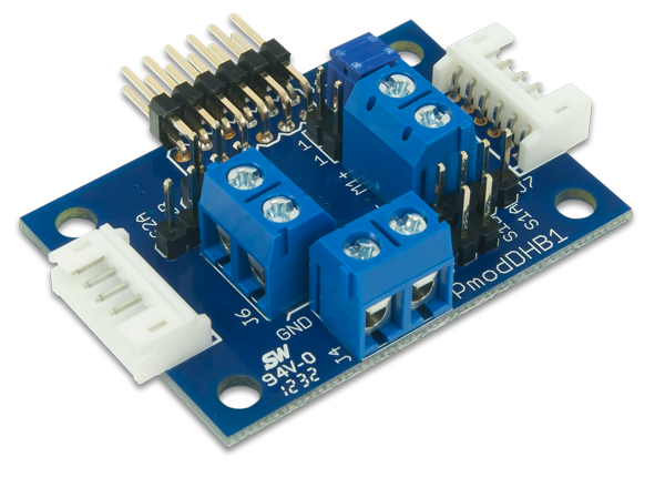
As you might suspect, the PmodDHB1 is also includes a dual H-Bridge (the DHB portion of the name), conveniently allowing this module to separately drive two DC motors in the same fashion as the PmodHB5. Because an H-Bridge has two signals to indicate the direction the motor should turn and the rate at which the motor should turn, the Pmod is able to use the four total signals from its two H-Bridges to drive a stepper motor. Stepper motors are a type of motor that do not have any physical contact between the motor shaft and the driving mechanism. Rather, there are a set of electromagnets that are concentrically spaced around the motor shaft.
When one of the electromagnets is “turned on” by a voltage signal available from the H-Bridge signal lines, the motor will be induced to rotate so that the teeth are as close as possible to the electromagnet. A second voltage signal can then turn on a second electromagnet immediately next to the first magnet and have the first electromagnet be “turned off” so that the motor shaft is free to rotate futher such that the teeth of the motor are now lined up with the second electromagnet. This cycle is able to continue with the remaining two magnets, creating an overall effect of having the motor spin in one full rotation through 4 “steps”; hence, the stepper motor. By using consistent timing intervals, both the PmodDHB1 and the PmodSTEP will easily drive a stepper motor in a smooth rotation.
If I choose a four-phase stepper motor, how should I choose ?