

Welcome back to the Digilent Blog!
We are going to continue with our Pmod series and talk about how you get the Pmod (peripheral module) to do what you want it to do. After all, it is not the best plan (especially in electronics) to just plug something in to a random spot and hope the device works correctly. The vast majority of the peripheral modules in the Pmod line collect or receive data (or both) and need to communicate this data with the host board. A GPS module that doesn’t send its coordinates to the host or an audio amplifier that does not receive data from the host are not terribly useful. Successful communication is key in any relationship, electronic or otherwise.
With the wide variety of Pmods available, there are also a number of communication styles different Pmods might use.
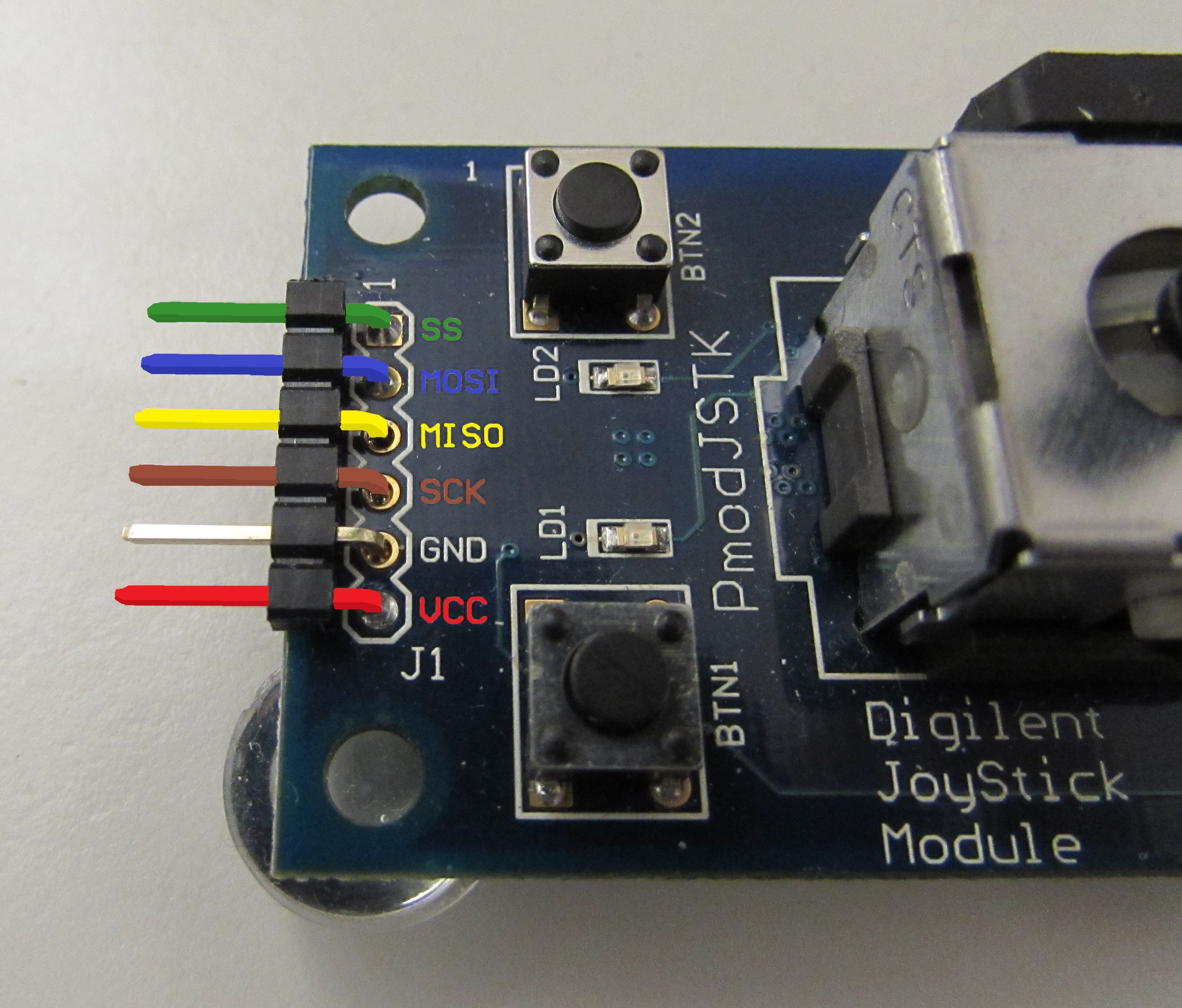
SPI (serial peripheral interface) is a useful communication style originally developed by Motorola. It uses four communication pins, along with a power and ground pin, so SPI is easily used with the 6-pin and 12-pin Pmod standards. In SPI, there is generally a “master” device (the host board) and a “slave” device (the Pmod) that communicate. To do so, the master will select one of its slaves with it’s slave select (SS) communication line to indicate to the Pmod that it is going to communicate with it. The master and the slave will then simultaneously communicate with each other (a full-duplex operation) on the MOSI (Master Out Slave In) and the MISO (Master In Slave Out) data lines. Both the master and the slave send one bit of information to each other after the master sends out a clock pulse on the SCK (serial clock) line to ensure that the timing of the data transfer is correct. Once a full byte, or eight bits of information, has been sent to the other device, the master (based on whatever code the programmer chooses) can either communicate again with the slave device or stop its communication with the slave device.
With its full-duplex capability, SPI is a fast communication standard. It can also support having multiple slave devices, but additional state-space (SS) data lines would need to be added, which takes up input/output pins on the host board that could have been used for other operations.
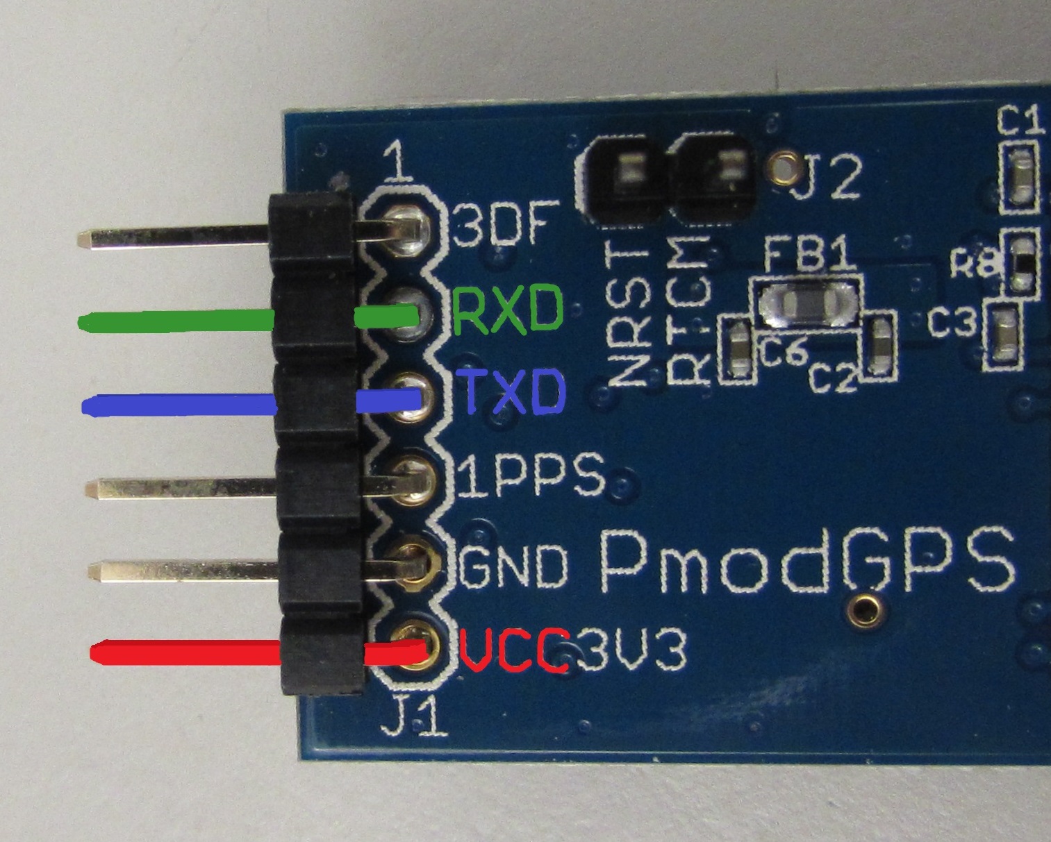
UART stands for a “universal asynchronous receiver/transmitter” and was developed by Gordon Bell at Digital Equipment Corporation in the 1960s. The “universal” portion refers to the format of the data and the speed of the transmission are configurable. UARTs are able to communicate in several different modes: full-duplex, half-duplex (the two devices communicate with each other one at a time), or simplex (the data communication is one way only). Because UARTs are configurable in their communication style, both the transmitting and receiving UARTs need to be configured in the exact same way to ensure that successful communication occurs.
UARTs are designed to communicate with other UARTs, although they generally do not directly generate the communication themselves; they only transmit and receive the signals. The transmitting UART will receive a byte from the host board, and then, using its internal shift register, first send a “start” bit to communicate to the receiving UART that information is about to be transferred. The byte of information is then sent one bit at a time, followed by a “stop” bit after the expected number of bits has been recieved, letting the communication line go high. The receiving UART takes the stream of bits and uses its SIPO shift register to make the data available to it’s host controller.
For the Pmod line, there are two different variations of UART that are used. The reason for this is primarily historical–at the time that UART pin interfaces were designed, microcontroller chips had completely separate SPI and UART interfaces that had no relation to each other. However, as newer microcontroller chips were developed, such as some of the newer PIC32s, they had serial interfaces that could work with both SPI and UART. To accommodate for this change, the UART interfaces on Pmods were also adjusted from the old standard so that they could easily share the same pins as the SPI pinouts.
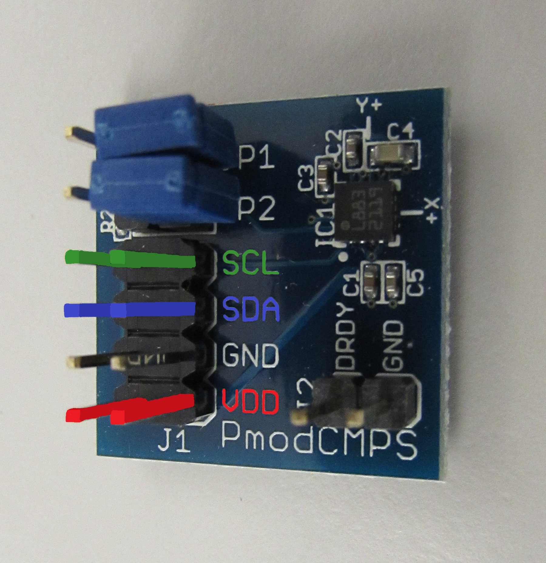
I²C (generally pronounced I-squared-C) is a communication style originally developed by Phillips Semiconductor (now NXP Semiconductor). In this protocol, originally intended to be part of the “Imod series“, only two communication pins are used: a serial data line (SDA) which is shared by both the master and slave devices, and an SCK, which the master controls. In the widely used 9-bit communication style of I²C, a master will pull the SDA low as the “START” condition to indicate that it wishes to communicate with a slave device and transmit two things–the 7-bit address of the slave it wishes to communicate with, and then either a read or write bit to show how it wants to communicate with the Pmod. For the 9th bit, and the 9th clock signal, a slave with the matching address will send an acknowledge (ACK) bit on the SDA line to show that it is ready to communicate. If there was no slave with the 7-bit address, the SDA line would be pulled up high during the 9th clock cycle and the master would interpret this as a not acknowledged (NAK) signal.
Assume that a Pmod does send an ACK signal, 9 more bits would then be transferred; the first 8 bits will be the information that is to be communicated either from the master or from the slave, depending if a read or write command was originally sent. If the master wants to keep sending information, it will wait to see if an ACK from the Pmod on the 9th clock cycle, or send an ACK response to the slave if it wants to receive more information from the slave. To end communication, the master may send a NAK signal after sending or receiving a byte of data for the 9th clock cycle. The master may then issue a “reSTART” to start a fresh communication or should release the SDA line as its “STOP” condition.
nbsp;
Although this communication style is not as fast as SPI (because it only operates in half-duplex), it is far easier to create a string or “daisy-chain” of I²C devices. This is because the Pmods that offer I²C communication styles have a 2×4 pin header for I²C, allowing for two sets of I²C. Additionally, because the communication style is set up where the master calls out a slave address as opposed to selecting a specific slave on its own line, only two input/output pins are ever needed for a I²C communication setup.
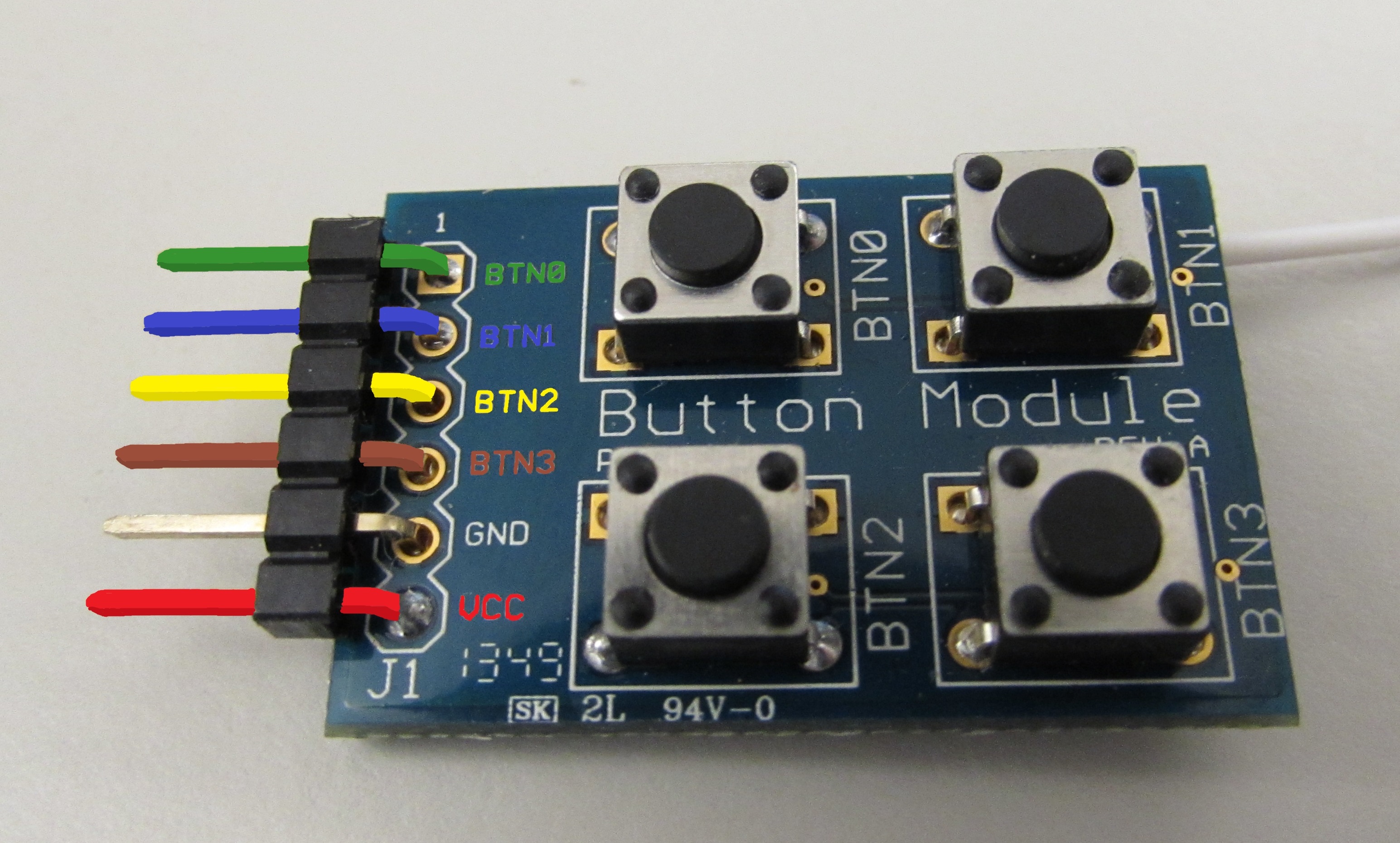
And finally, Pmods also communicate with the host board through general purpose input/output (GPIO) pins. This does not follow follow a strict set of rules regarding how the Pmod and the host should communicate. Rather, the host is able to send high, low, pulse-width modulation (PWM), analog, audio, and a variety of other signal types to the Pmod at any time and have the Pmod respond (more or less) immediately. This is great if you want to get a response whenever you press a button or flip a switch. The host could also receive the same variety of signals from the Pmod at any time, but it depends on how the code is designed to have the host respond to or ignore the signals. Also, because we are using input/output pins for communication, we can become rapidly limited in our capability to operate a large amount of peripheral modules.
Example Application: if you’re designing a motion-detecting application, consider using the Pmod Passive Infrared Motion Sensor. The Pmod PIR communicates through the GPIO pins and can easily integrate with various host boards. It’s designed to detect motion through passive infrared sensors, which is perfect for applications like security systems, automation, or even interactive displays.
In setups where a direct Pmod connection isn’t practical—such as when using breadboards, jumper wires, or custom wiring—something like the Pmod CON1 Wire Terminal Connectors can make integration much easier. These allow secure wire connections without needing a standard Pmod header on your host board.
And now for our bonus historic information! You may have noticed that a few of these communication styles keep the data communication line in a high, or powered, state when they waiting for a new communication to occur. This is leftover from the telegraph era where the communication line was held in a high voltage state when it was not being used to show that neither the line nor the transmitter were damaged.
Good morning James
I am learning VHDL, could you please provide me a VHDL code for an SPI interface to communicate with a Nexys 4 ddr, please Sr?
I would appreciate it.
Regards.
Hi Sergio,
I apologize for not getting back to you sooner. I don’t personally know how you would write some VHDL code for a SPI interface; I would recommend posting your question on Digilent’s technical forum, https://forum.blog.digilentinc.com, where one of our applications engineers would be better suited to help you.