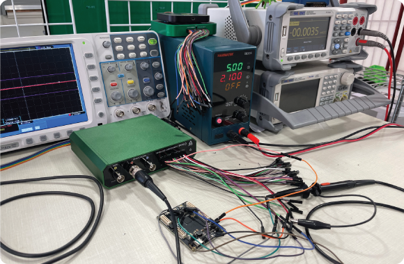
We recently published a whitepaper “Precision Debugging with the Analog Discovery Pro (ADP2230)”. This whitepaper was originally going to be using the Analog Discovery 3, however, as can be seen in the name of the paper, we didn’t end up going with that. That begs the question: Why? The paper, includes recording a relatively long series of SPI transactions, part of the boot sequence for an FPGA. Back when we were working on this in early August, after the first draft was done, we realized that the 32k input buffers of the AD3 weren’t going to be big enough for this transaction. A fair bit of discussion about what to do about this issue and how to fix it followed.
Let’s explain: The whitepaper involves recording 200k digital samples over a time period of 4 ms, with a sample rate of 50 MS/s. The AD3 features 32 kS input buffers – clearly this is not enough memory to store the entire transaction locally. The AD3 (and all of our other WaveForms-supported T&M devices) features a Record mode, which allows the device to stream data back to a host, bypassing the buffers. However, in record mode, max sample rates can be limited by the connection between the device and host. The AD3 can stream around 10 MS/s back to a host over USB, which was also insufficient for this task.
So, what do you do when you realize your instrument isn’t best suited to the task you’re trying to make it perform? You can find manual workarounds, you can try to leverage complex features of the device to get an automatic workaround, or you can upgrade. Let’s go through these in order:
1. We could rewrite the paper to make better use of the Analog Discovery 3. This could have involved only checking the Chip Select signal for the full transaction time, then zooming in on a narrow portion of the transfer, which could fit into a single 32 kS acquisition, to check the other signals. That said, in a real-life scenario, where you’re trying to find a bug that could occur anywhere in a long period of time, using this approach could get tedious, requiring you to make many acquisitions, adjusting the trigger position and time base every time, to find the one spot where an error occurred. The more samples and the longer the acquisition, the worse the prospects get.
2. We could use other features of the Analog Discovery 3 to reduce the amount of data moving over USB.
3. We investigated the data compression feature of the logic analyzer instrument. This feature is capable of significantly reducing the amount of space an acquisition takes up, by storing only the samples where the state of any active DIO line changed, in addition to a time stamp indicating how long it had been since the last sample was taken. With 16-bit samples and 16-bit timestamps, if the state changes in less than 50% of samples, this immediately starts to reduce the amount of data captured. Unfortunately, this feature did not help in this specific case, due to the SPI clock frequency being high enough that USB still couldn’t handle it, with only a ~1.25x reduction (SPI clock has two states, runs at 10 MHz, with sampling rate of 50 MHz, and memory usage is doubled for timestamps) in data rate.
4. We also briefly looked into using the SPI clock to sample the incoming data. The Logic Instrument has a Sync mode that can be used to use one of the digital inputs as the instrument’s clock. With this, data is sampled on the rising or falling edge of that DIO. In this case, it might have reduced the amount of data captured by 5x, which might have been able to fit through USB, however, it would also lose us the ability to check some properties of the SPI bus. For example, we wouldn’t be able to double check the clock polarity.
5. We could just use a different, more capable device. This is the one we went with. Since all the issues stemmed from the input buffers on the AD3 being too small to fit the acquisition we wanted to do, we would need a device with larger buffers. Any of the Analog Discovery Pro line devices are capable of this. The ADP3450 and ADP3250 have DDR memory that lets the logic analyzer buffers store up to 64 MS per channel in Record mode. A recent WaveForms update upgraded the ADP3450/ADP3250’s capabilities by adding the ability to stream acquisitions into DDR memory at the full sample rate of the device. The same feature was introduced for the Eclypse Z7 image that adds WaveForms support to that device. The ADP5250 could also handle it, with an MS of buffer per channel. We decided to go with the newest addition to the Analog Discovery Pro line – the ADP2230 – which makes these devices more accessible by providing the lowest-cost option to feature deep memory buffers – up to 128 MS per channel for the digital inputs.
Creating the whitepaper “Precision Debugging with the Analog Discovery Pro (ADP2230)” emphasized to us the importance of selecting the right tools. When faced with challenges like using the small memory buffers of the Analog Discovery 3 to record for a long period of time, exploring various strategies is crucial. From investigating manual solutions to upgrading to the ADP2230, thoughtful tool selection is essential for attaining accurate debugging results. Moving forward, we urge readers to assess their instrumentation needs carefully. Explore our shop pages on Digilent’s website for our product range, including the Analog Discovery Pro line, specifically the newest addition, the Analog Discovery Pro (ADP2230).
Access additional resources in Reference and get answers to specific questions in our user forum.


