An XLR cable is what is commonly used with microphones and are also referred to as “balanced” cables. For years I have ignored a nagging question in my head:Why are there 3 pins on an XLR cable? I figured two could be explained as a signal transmitter and a ground, but what is that other pin doing there? And XLR seems to suggest a ground, left, and right signal like as if it was outputting a stereo signal, but a single microphone is a mono signal. Surely, there must be a reason for this third pin. Well, I looked it up and was fascinated by what I learned and wanted to share it with you!
First, we need to cover a little bit of wave theory to make sure we are all on the same page. The following examples are chosen for a reason that will hopefully become clear when we get back to the XLR discussion. I will use Desmos online graphing calculator to generate graphic examples. Say you have a basic cosine wave given by the equation y = cos(x) and looks like this:

Second, say you have another basic cosine wave with a 180 degree phase shift (which would equivalently be a negative sine wave) given by the equation y=cos(x+π) and looks like this:

Now, if you were to add these two waves together, the resulting wave is the addition of every infinitesimal point along the curve. For example, the the value of the first wave at x=0 is 1 and the value of the second wave at x=0 is -1, so if these wave are added together, the resulting value at x=o is 1+(-1) which equals 0. In fact, every point along these curves are equal and opposite in value so adding these two waves by the equation y=cos(x+π)+cos(x) will result in zero for all values of x:

These two signals would also be referred to as being “completely out of phase”, which just means that when these two waves are added together, the result is a flat line. If these were originally sound waves (all sound waves are dynamic, not flat lines) then adding them together would result in silence. This is a very important issue to address when recording a sound with multiple microphones, commonly referred to as “phase issues” – more on that later.
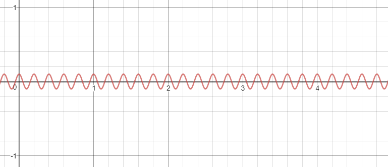
Okay, one more example then back to the XLR cable mystery. Let’s say you have a noise signal, high frequency and low magnitude, given by the equation y=0.1cos(10πx) that looks something like this:

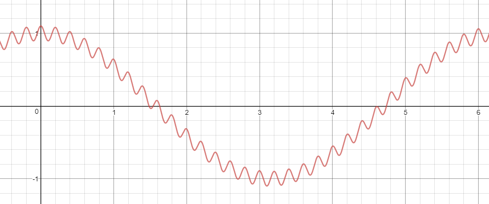
If you were to add the noise signal to our first wave, such as y=cos(x) + 0.1cos(10πx), we would see something like this:

Which is a good example of a distorted signal that has picked up some noise (environmental electrical or magnetic noise is everywhere). When using a microphone, the mic pics up not only the sound waves going to it, but also noise that would distort the signal like this previous example. Ready for the fun part? This is where the three pins of an XLR come into play.
Of course, one pin is a ground reference. However, the other two pins are there to compensate for inevitable noise in the raw signal. This is the magical part. One pin sends the signal as is, and the other pin sends the signal with opposite polarity by referencing its voltage opposite to ground from that of the other pin which can be illustrated as a 180 degrees out of phase, just like the first two wave examples in this post. The thing is, that both pins will pick up the same noise but that noise will not be out of phase between the two pins, so it would be like adding the noise wave example to the first two example waves like this:

The red curve is the original signal and the green curve is the opposite polarity signal (in this case, equivalent to a 180 degree phase shift – the addition of pi is the radian equivalent to a 180 degree phase shift) to This is what the L and R pin would essentially look like coming out of the microphone. Now, the clever trick is that when both signals reach the input to whatever the mic cable is going to (amplifier, mixing board, etc.), one of the signals are inverted and added to the other signal. The inversion basically switches the polarity of one signal so that they are referencing ground equivalently (which, again for this case, can be illustrated as a 180 degree phase shift). This inversion puts both signals completely in phase but renders the noise that was common to both signals completely out of phase, so when they get added together, the noise is removed from the signal!

The minus signs on the green wave take care of the inversion, which you can see now lines up perfectly in phase with the red wave. However, note that the noise that each signal picked up is now completely out of phase. When the two waves are added together (the blue wave), the noise is removed! Notice that the blue wave is smooth without the noise distortion. I don’t about you, but I thought that was some clever stuff!
I hope this was informative and clear to understand. Please comment if anything needs more clarification or if you have any other questions or input regarding the theory behind this. There are other mathematical approaches to this concept.


If the noise is present on two of the conductors in the cable, what’s to prevent it from being present on the third conductor (i.e. the ground)? And if the noise is present on the ground, the noise will get still be apparent because of the difference between the noisy-ground and the now clean-signal…
I’m sure there’s an answer, I just don’t know it from this discussion.
Hi Chris!
Thanks for reading. The noise I am referring to in this article is environmental noise that becomes mixed with the input signal. That signal is only sent on the two conductors and not the ground pin. The ground is a voltage reference and does not conduct the signal. However, there are other sources of noise when it comes to XLR cables and audio transmission. For example, if multiple systems are being used together and their ground pins are at different voltages, you will experience a “ground loop” noise. That type of noise is different than the environmental/EMI/RFI noises that are picked up on the two conductors and cancelled out by a differential amplifier on the receiving end. Does that make sense?
You mention L & R mic connections. This could be confusing as the standard XLR-3 pin connector is numbered 1, 2, 3 and refers to a single channel for every balanced circuit connection. Most connection standards use #2 as the Hot, #1 as Cold & #3 as Earth.
For a BALANCED single mic using the XLR-3 connection standard you will only see the 3 connections be it dynamic or condenser type but if it’s a true L & R stereo type mic it will contain two individual mics arranged to capture the stereo sound image. The connection will likely use an XLR -5 setup and commit 2 channels of the audio mixer.
An UNBALANCED mic that’s designed as a stereo unit ( two separate integral capsules) will often use a common Earth (cold) and the other two connections as L & R (hot) but terminate with a ⅛” (3.5 mm) jack plug.
Hi Pete!
You are very right. I fell short on proper pin references and mentioning that there are microphones that are true stereo. Thank you for commenting with your input.
Hi Ian,
I enjoyed reading your blog. I had thought about the same question in the past.
Minor nitpick: In paragraph 3, cos (x+π) = – cos (x), but sin x = cos (x-π/2).
Hi Julian!
Thanks for reading. You’re right, I should’ve said a negative sine wave in paragraph 3. Thanks for your input.