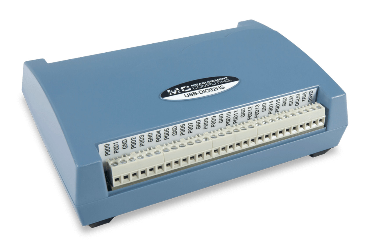
Digital I/O
Digital I/O DAQ (Data Acquisition) devices are systems designed to manage and monitor digital signals in various applications. These devices can send and receive digital data, making them essential for tasks like controlling external hardware, monitoring digital states, or interfacing with other electronic systems. They are commonly used in automation, testing, and industrial processes where precise digital control or monitoring is required.
The "I/O" in their name refers to "input" and "output," indicating their dual functionality. Digital input channels allow the device to detect and monitor the state of digital signals, such as the on/off status of switches or the logic levels of circuits. Digital output channels enable the device to control or trigger external components, such as LEDs, motors, or relays, by sending specific digital signals.
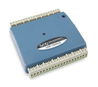
Electromechanical Relay USB Devices
- USB-ERB08: Eight single-pole double-throw (SPDT) Form C electromechanical relays directly controlled by digital I/O lines.
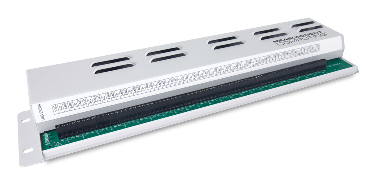
- USB-ERB24: 24 single-pole double-throw (SPDT) Form C electromechanical relays directly controlled by digital I/O lines.
- USB-ERB08: Supports configurations as two banks of four.
- USB-ERB24: Supports configurations as two banks of eight and two banks of four
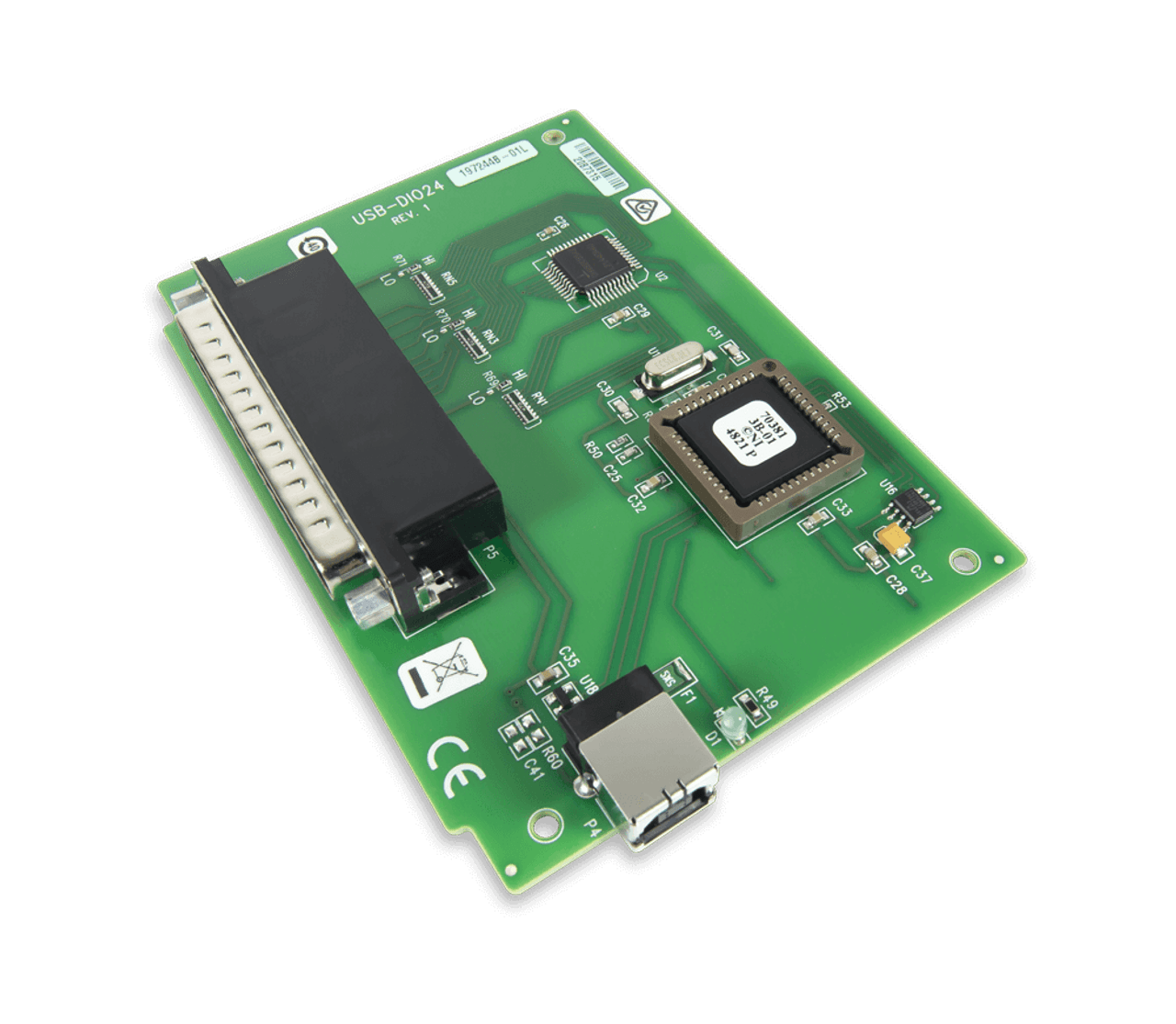
24-Channel Digital I/O USB Devices
- The 37-pin connector provides 24 digital I/O, one counter, six ground, and two power connections
- The digital I/O port is configured as two 8-bit and two 4-bit ports based on an 82C55 mode 0 emulation
- The CTR signal is the input to the 32-bit external event counter
- 5.5 V max inout voltage
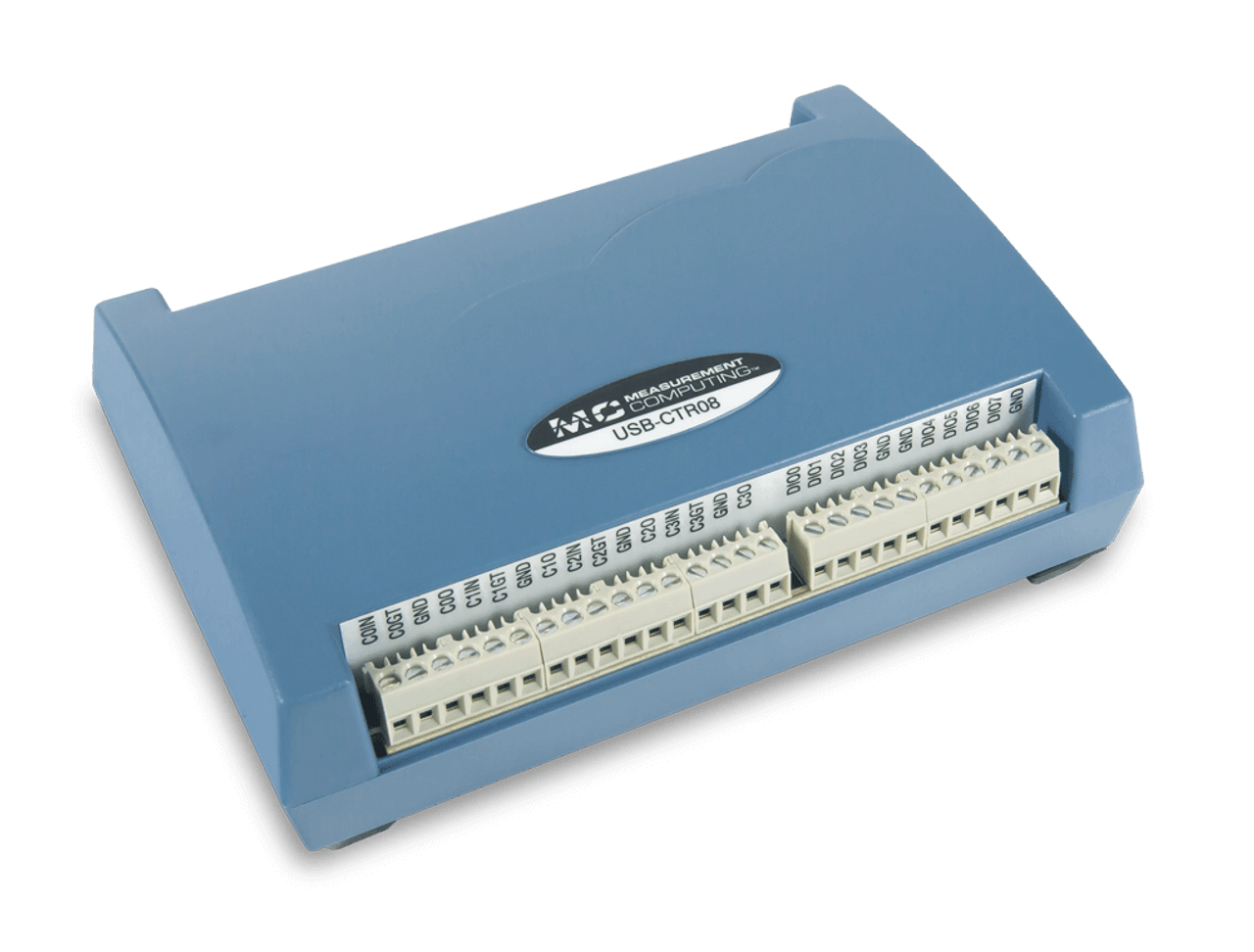
High-Speed Counter / Timer USB Devices
- USB-CTR04: Four counter inputs
- USB-CTR08: Eight counter inputs
- 48 MHz maximum input frequency
- Software-selectable resolution up to 64-bits
- Aggregate scan rate of 8 MB/s
- Supports Totalize, Period, Pulse width, and Timing counter input modes
- Four independent pulse-width modulation (PWM) timers
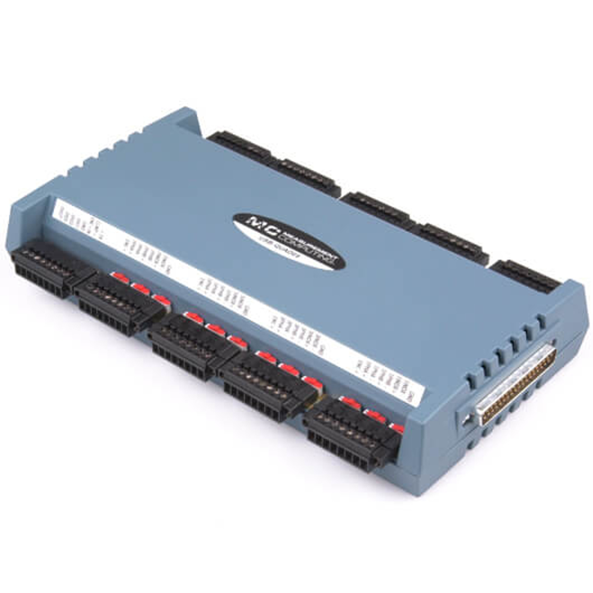
Quadrature Encoder USB Device
- Eight counter inputs (quadrature/non-quadrature mode)
- Simultaneous input and decoding of up to eight incremental quadrature encoders
- High-speed pulse counter for general counting applications; multiple counting modes supported
- Configurable as single-ended or differential
- 10 MHz, 16-, 32, 48-bit resolution, ± 12 V input range
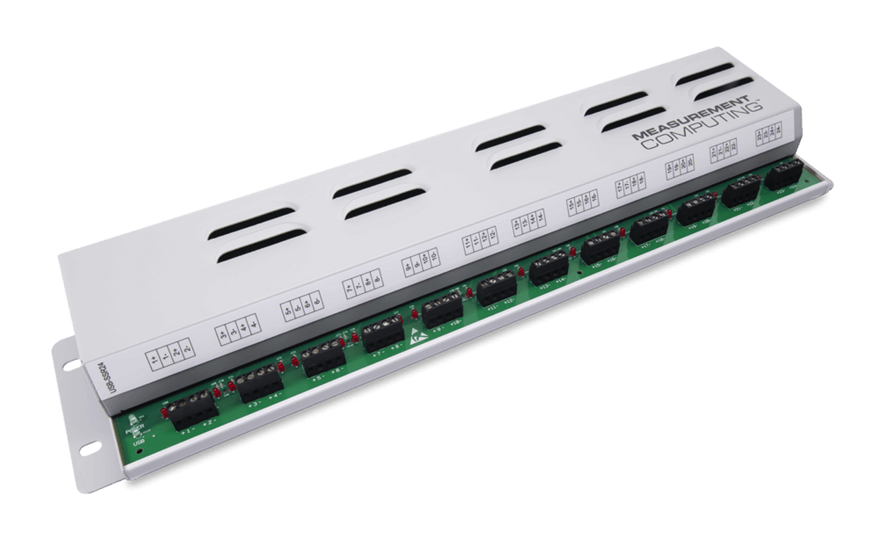
24 Channel Solid-State Digital I/O USB device
- Mounting rack for 24 solid state relay (SSR) modules (backplane is divided into two groups of eight modules and two groups of four modules)
- Onboard switch to configure the module type (input or output) for each module group (you cannot mix input and output modules within a group)
- Onboard switch to configure the control logic polarity (active high or low) for each module group


