I’m a big fan of the chipKIT WF32. It’s a powerful little board with a WiFi card and SD card reader built in, but there’s a lot more to this board than meets the eye. There are a ton of communication lines, external interrupts, output compare pins, and more hidden in all those GPIO pins, but how do you tell what is what? That’s where the WF32 pin diagram comes in. I’ve compiled, color coded, and listed what each pin is capable of.
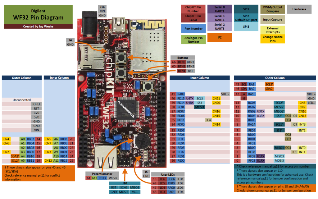
You can find all sorts of useful information on here about what each pin can do. For example, there are five PWM capable pins on board, four external interrupts, and twenty change notice pins! This will also tell you which pins are connected to the on-board hardware, like the potentiometer and buttons. This diagram is crazy useful, but it’s not quite complete without the WF32’s reference manual.
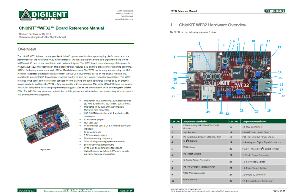
Check that out for information about how to connect jumpers to access certain signals and which pin numbers to address when you do. Whenever you use SPI, I2C, or UART, you’ll want to read the reference manual’s sections on those first. The reference manual can tell you a great deal more than the pin diagram ever could, such as which communication ports are dedicated to the WiFi card and SD card, information about the power supplies and voltage compatibility, and how much power can be out-put to the pins all at once. The pinout tables for the WF32 are also in the reference manual, organized by chipKIT pin number, port bit, or PIC32 pin number.
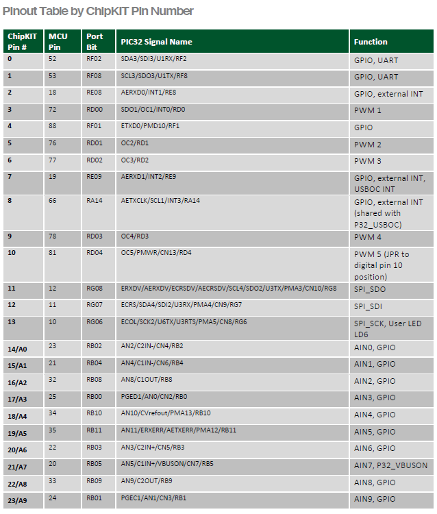
These are functionally very similar to the pin diagram, but contain far, far more information about what signals and functions are connected to each pin. That’s too much information for most new users to handle all at once, and they’re not as user-friendly as the pin diagrams, but once you get used to them they can be a very useful reference. The final part of this reference tri-fecta is the WF32’s board-defs.
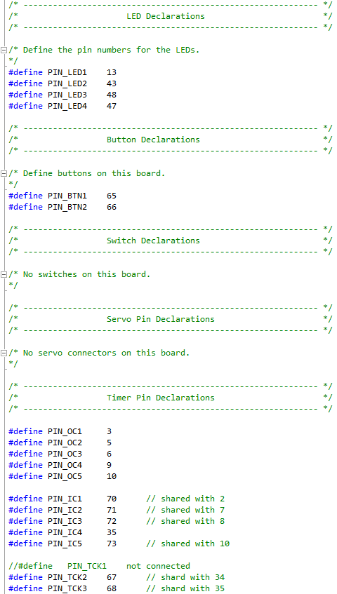
I wrote an Instructable earlier this week about how to access these (on Mac and Windows), and how to use them. MPIDE uses these to tell what signals are on what pins, but they’re readable enough that you can use them too! Not only could they tell you things like, say… which pin LED1 is connected to, they could also tell you how to refer to LED1 directly in your code and not just its pin number! That way everybody knows what you’re talking about. Lastly, if you’re feeling up to it, I’ll point you to the schematic for the WF32.
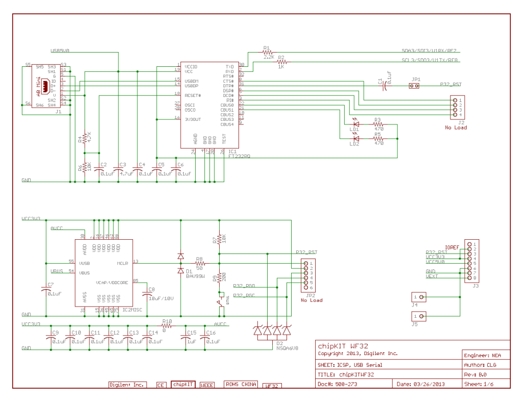
These are a little too in-depth to appeal to most users, but I’ll give you a little hint that can help out a great deal. If you look on your board, each jumper, pin header, even the LEDs and buttons all have a label. You can find these labels in the schematics, and from there it’s not too difficult to figure out which pin is which. From here, the schematic tells you not only which pins are connected to what signal, they also show you which jumpers connect what, and which signals go through resistors or diodes before reaching the pin. Whenever I have an issue figuring out what’s going on with the pinout tables, I go straight to the schematics for a clear, no-nonsense, illustration of what connects to where. With those documents, you should be able to find out everything you need to know about the WF32 hardware. Before I go, however, I want to point out that while there isn’t a pin diagram for the other chipKIT boards yet, all the other documents (the reference manual with pinout tables, board-defs, and board schematics) are available for every chipKIT board through DigilentInc.com. Just scroll to the very bottom of the product page and you’ll find links for all these docs, as well as libraries and helpful example projects. Now you should be well prepared for your own projects! Good luck!


Having just developed the Harmony BSP for the WF32, I noticed that the pin diagram doesn’t include the pin names for the buttons (RA6 and RA7).