

In the vast realm of data acquisition, the precision and accuracy of measurements—particularly when working with digital input/output (I/O)—play a crucial role in extracting meaningful insights. This Tech Tip will help you dive into the intricacies of signal conditioning and explore the fundamental principles behind this vital process. Unraveling the complexities of noise reduction, amplification, and filtering techniques, we uncover the secrets to achieving optimal data integrity and maximizing the potential of your data acquisition system.
Pull-up and Pull-down Resistors
When a device is powered on or reset, digital I/O pins are usually, by design, set to high impedance input. There may be enough drive current available from the inputs to turn on any connected output devices, such as solid state relays (SSRs).
To prevent unwanted switching, and to drive digital outputs to a known, safe state after power-on or reset, pull all digital pins either high or low with a pull-up or pull-down resistor.
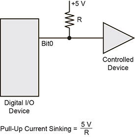
| Pull-up Resistor With a pull-up configuration, I/O lines connect to logic power through resistors. When the digital I/O device is reset, it enters a high impedance input mode, and the I/O lines are pulled high. The digital I/O device and attached devices sense the high signal. A board that is in output mode has enough power to override the pull-up resistor’s high signal and drive the line low to 0 volts. |
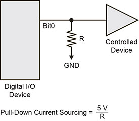
Pull-down Resistor With a pull-down configuration, I/O lines connect to logic ground through resistors. When the digital I/O device is reset, it enters high impedance input mode, and the I/O lines are pulled low. The digital I/O device and attached devices sense the low signal. A board that is in output mode has enough power to override the pull-down resistor’s low signal and drive the lines high to 5 volts. |
|
 |
 |
USB-based digital I/O devices from Digilent’s MCC DAQ products are designed with built-in pull resistors.
TTL to Solid State Relays
Many applications require digital outputs to switch high AC and DC voltages on and off, and to monitor the presence or absence of high AC and DC voltages. However, high voltages cannot be controlled or read directly by the TTL digital lines of a device. Use SSRs to control and monitor AC and high DC voltages, and to provide >1000 V of isolation. SSRs are the recommended method to interface with AC and high DC signals.
Voltage Dividers
To detect a signal with a common ground, but that varies over a range greater than the maximum input specification of a digital input, consider using a voltage divider or some other external device to reduce the voltage of the input signal to a safe level. Note that this method does not provide isolation.
Ohm’s law states that Voltage = Current × Resistance
In a voltage divider, the voltage across either one of the resistors in a circuit is proportional to its resistance versus the total resistance of the circuit.
The objective in using a voltage divider is to choose two resistors with the proper proportions, to achieve the desired reduction percentage of the input voltage.
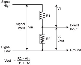
Figure 3. Voltage divider schematic
Dropping the voltage proportionally is called attenuation. The variable attenuation is the proportional difference between the desired output voltage (the maximum device input voltage) and the full input voltage from the field device. The formula to calculate attenuation is:
Attenuation = R1 + R2
For example, if the field voltage varies between 0 and 10 volts, and you wish to detect that with a maximum device input voltage of 5 volts, the attenuation must be 2:1 or simply 2.
2 = 10K + 10K
For a given attenuation (A), pick a handy resistor and call it R2, then use this formula to calculate R1:
R1 = (A – 1) x R2
Digital inputs often require voltage dividers. For example, to detect a field signal that is at 0 volts when off and 24 volts when on, you cannot connect the signal directly to the digital inputs of most boards (an exception is the Measurement Computing PDISO series). The voltage must be dropped to 5 volts maximum when on. The attenuation required is 24:5 or 4.8. Use the equation above to find an appropriate value for R1 if R2 is 1 kOhm. Remember that a TTL input is on when the input voltage is greater than 2.5 volts.
Calculating the Power Dissipation in the Divider Circuit
Resistors R1 and R2 are going to dissipate all the power in the divider circuit according to the equation:
Current = Voltage ÷ Resistance
The higher the resistance value (R1 + R2), the less power is dissipated by the divider circuit. As a simple rule:
- For attenuation of 5:1 or less, no resistor should be less than 10 kOhm.
- For attenuation greater than 5:1, no resistor should be less than 1 kOhm.
Low-pass Filter to De-bounce Inputs
An input signal may experience noise attributable to an external component in a circuit generating the signal to be monitored. The external component is often a mechanical switch.
To decrease this noise, use a low-pass filter on the signal wires between the signal source and the digital device. A low-pass filter prevents frequencies greater than the cut off frequency from entering the digital inputs on the digital device.
The cut-off frequency is the frequency above which no variation of voltage, with respect to time, may enter the circuit. For example, if a low-pass filter has a cut-off frequency of 30 Hz, the interference associated with line voltage (60 Hz) would be mostly filtered out. However, a signal of 25 Hz would pass with less attenuation.
In a digital circuit, a low-pass filter might be used to debounce, or filter, an input from a switch or external relay. If the switch/relay contacts are mercury-whetted, however, they tend to bounce briefly on closure, generating a pulsating noise signal.
The figure below shows a simple low-pass filter that is constructed from one resistor (R) and one capacitor (C).
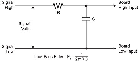
Figure 4. Low-pass filter schematic
The cut-off frequency is determined according to the formula:
|
Fc = 1/(2πRC) |
Where π = 3.14… |
|
R = 1/(2πCFc) |
If you have any questions or if you would like any further information, please visit the Digilent Forum.