

Acquiring voltage signal data during tests is essential, particularly after investing substantial time and resources in the testing process. It’s imperative to preserve this test data to prevent loss and ensure that no significant events are overlooked. To quote an iconic fictional character “Life moves pretty fast; if you don’t stop and look around once in a while, you could miss it!” How can unforeseen events be captured while sampling at high signal rates, enabling subsequent analysis of the data surrounding each triggered event? Digilent’s Analog Discovery Pro (ADP2230) can capture data samples from thousands of rapidly triggered events to buffers in the on-device memory, up to a total of 128 MS per channel. Capturing only specific events, as opposed to capturing continuously, reduces the amount of data transferred over USB to buffers on a host for analysis. Post acquisition, users can scan each data buffer for the triggered event.
Memory segmentation is the process of allocating blocks of memory for triggered events, so only a set amount of data per specific event is captured into the on-device memory. Using WaveForms’ Oscilloscope, Logic, and Spectrum instruments, the ADP2230 supports device buffering (memory segmentation), at sampling rates up to 100 MHz, allowing for rapid triggers with blind times as low as ~2 μs between acquisitions. In other words, a minimum time delay or rearm time between two triggered buffers is ~2 μs. (The Analog Discovery Pro 3000-series and Eclypse Z7 support a blind time <1 μs.) These Test & Measurement devices contain on-device DDR memory which can be split into multiple segments (memory segmentation) and the device is configured so that it can rearm itself, enabling consecutive triggers to occur rapidly without requiring USB communication from a software application each time. This design allows for high-speed data capture where users can focus on triggered sections of an input signal. Since only triggered data is recorded, the device transmits a smaller volume of data via USB to WaveForms running on the host system for processing. This approach mitigates bottlenecks in comparison to continuous acquisition without triggering.
Traditionally, when attempting to retrigger an acquisition, data is captured by the device and then sent to the host system for the software application to instruct the device to rearm itself for the next capture. The time taken for the application to communicate with the data acquisition device via USB results in a delay potentially 10s of milliseconds or more between captures, resulting in missed trigger events. With device buffering, the memory is divided into multiple segments for capturing data, with a dedicated section reserved for the capture information table. This configuration enables the device to execute multiple captures by utilizing the memory segments as a First-In-First-Out (FIFO) mechanism. The software reads the captures sequentially, freeing up memory for reuse in subsequent captures. The deep memory on-device aids to capture triggered data buffers at faster sampling rates, while displaying the data on the host system. Improved rearm time (low latency captures) is the main benefit of the device buffering.
Dependence on device buffering alone doesn’t guarantee the ability to analyze significantly more acquisitions than usual. It’s still necessary to visually inspect the screen or navigate through previous acquisitions to ensure nothing is overlooked. Additionally, because measurements are conducted in software, rapid triggering doesn’t provide the capability to selectively collect pulse heights while discarding unnecessary acquired data.
Configuring WaveForms for Device Buffering with an ADP2230
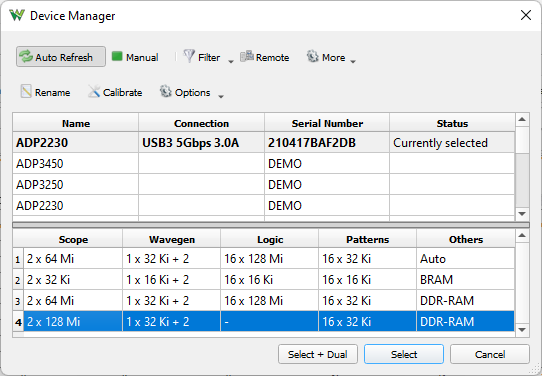
In order to use device buffering with an ADP2230, either the third or fourth memory configuration option (using DDR-RAM) must be selected via the WaveForms’ Device Manager window. The BRAM option does not have enough deep memory to support device buffering for rapid triggers.
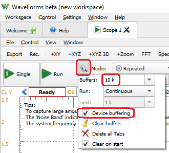
Using the Scope instrument’s Control toolbar, a user can enable Device Buffering, specify the number of buffers to be stored on the host system (up to 10,000 in a circular array), and set the acquisition to a continuous run or to stop when the specified buffers or limit number of captures are collected.
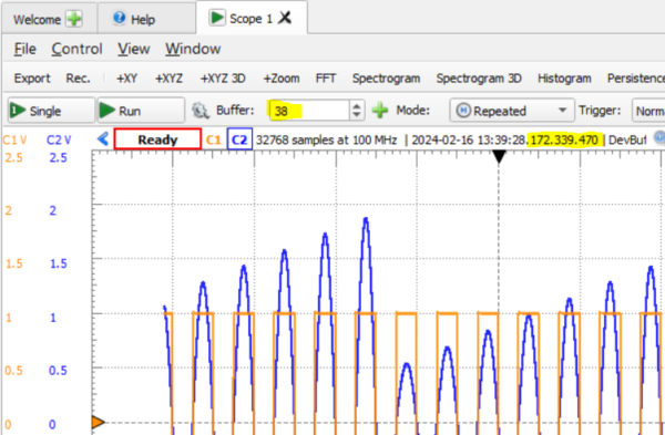
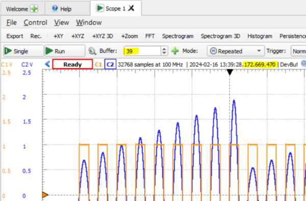
The buffer samples size is set by the user in WaveForms’ Time group window. The number of device buffers (segmented blocks in DDR) is determined by the ‘Scope capture memory / specified Time-Samples / Enabled device channels’ and is shown above the main plot in the time header as DevBuf: used/total, with a maximum count of 32,768.
The trigger option within the Control toolbar can be set up to activate based on the source channel, signal condition, and signal level. Data is stored in buffers according to triggered events.

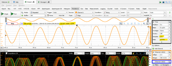
With Device Buffering, the blind time extends only by a few microseconds beyond each acquired buffer duration. The variance in capture timestamps indicated in the plot headers below demonstrates the delay between captured buffers.
The Persistence view specifically overlays all received buffers in the WaveForms software, creating a heatmap illustrating the typical movement of a signal relative to the trigger. This view proves handy for spotting glitches or capturing a rare event amidst a series of typical occurrences. The regions with the highest density appear red (hot), whereas those with the lowest density appear blue (cold).
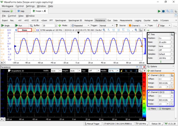
Figure 7: The Persistence view of 20 buffered acquisitions.
The Measurements view can be used with multiple buffers and enables various types of post-processing on acquired data, such as identifying the minimum or maximum measured voltage without the need to manually inspect each individual capture.
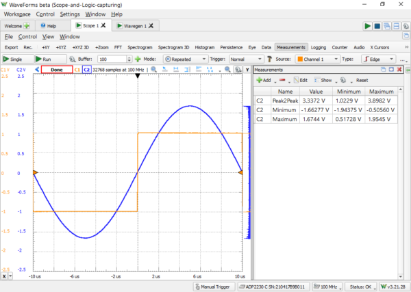
Figure 8: Identifying min/max peaks across multiple buffers.
Conclusion
Digilent Test and Measurement devices, such as the ADP2230, ADP3250, ADP3450, and Eclypse Z7, have more on-device memory to capture triggered data buffers at faster sampling rates, while displaying the data on the host system. The “Device Buffering” feature’s main benefit is reducing blind time and improving rearm time, which is enabled by the ability of devices that support it to store buffers in hardware. Without this feature, you would lose trigger events while the capture is transferred, potentially 10s of milliseconds or more worth of data between captures, depending on the capture size, USB bandwidth, and host system resources.
This feature proves useful when searching for uncommon occurrences within a received signal. It allows you to conduct numerous standard acquisitions and subsequently review them to identify anomalies. Moreover, it facilitates the accumulation of data regarding the consistent performance of your circuit during multiple test iterations, helping you determine whether your circuit exhibits consistent behavior across multiple tests.
In essence, the key point is that device buffering caters mainly to users deeply concerned with rearm time. While multiple acquisitions and software buffers have broader utility, serving purposes like persistence, measurements, and revisiting previous signal acquisitions, device buffering isn’t indispensable for these functionalities. That said, for users interested in these features, rearm time can be a key concern and, when it crops up, device buffering solves these issues.
You can check out WaveForms support for the ADP2230 by downloading the latest WaveForms beta release, available in this thread on the Digilent Forum
For additional information regarding the ADP2230, visit its resource page.
For additional information regarding multiple acquisitions in WaveForms, reference the Working with Multiple Acquisition Buffers in WaveForms guide.
I’m confused by Figure 5 and 6. The text says that there is only a few microseconds of difference beyond each acquired buffer acquisition, but the difference between the time stamps is 330 microseconds, which is more than “a few”.
What am I missing?