

Options are nice, right? Especially when it comes to analyzing a circuit. Different tools may offer different benefits and drawbacks for certain applications. That’s why the Analog Discovery Studio has two options for the Oscilloscope and Waveform Generator connections to your circuit: MTE (Measurement and Test Equipment) and BNC
(Bayonet Neill–Concelman).
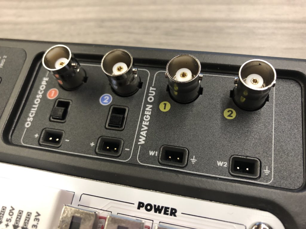
Analog Discovery Studio. The BNC connections are the cylindrical ports on
the top and the MTE connections are the recessed two-pin ports on the bottom.
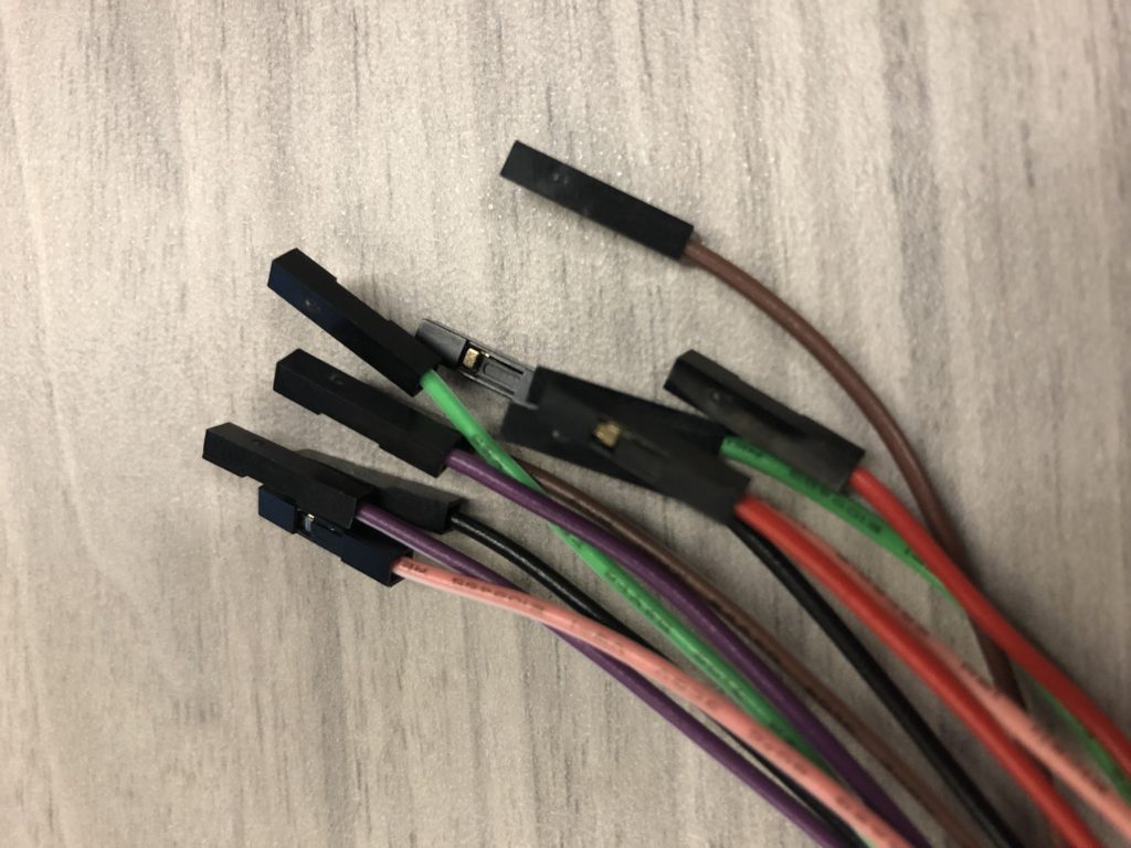
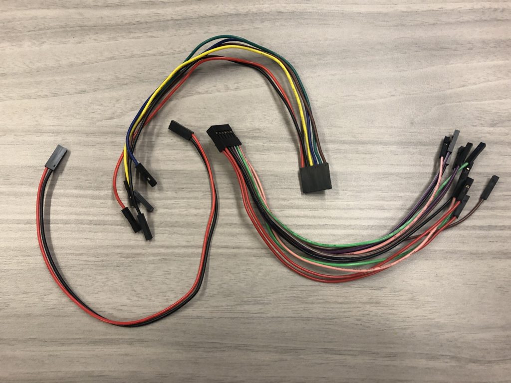
MTE connections are common among all Digilent Test and Measurement products. The MTE oscilloscope connection provides a differential measurement, allowing circuit tinkerers to measure and analyze circuit elements or blocks with respect to whatever reference the user desires. This can be helpful for confirming specific voltage drops, filter outputs, or other waveform properties that benefit from a differential measurement. The MTE cables are also very breadboard friendly, as they are small, short, easy to manipulate, and quick to connect to your Analog Discovery Studio Canvas. MTE connections are also convenient for connecting to microcontroller or FPGA header pins, due to the square, plastic female or male tip. However, using many MTE connections can risk introducing noise to your signals, especially at high speeds.
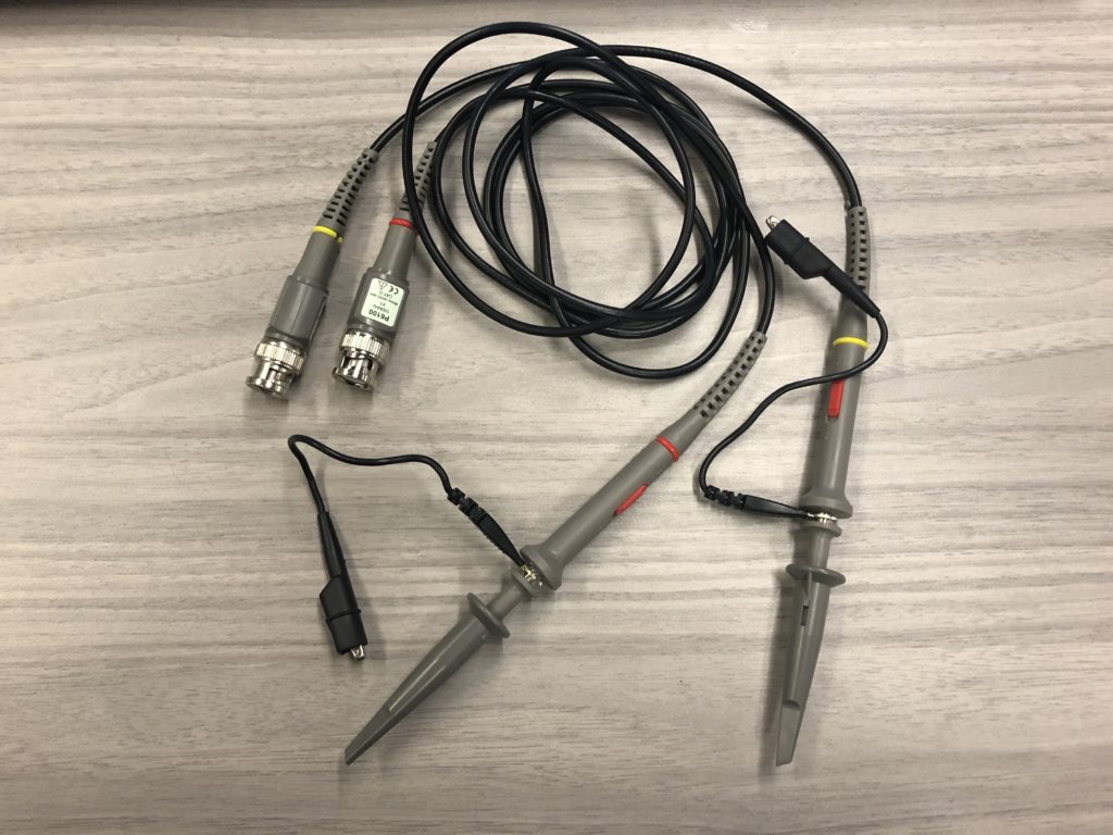
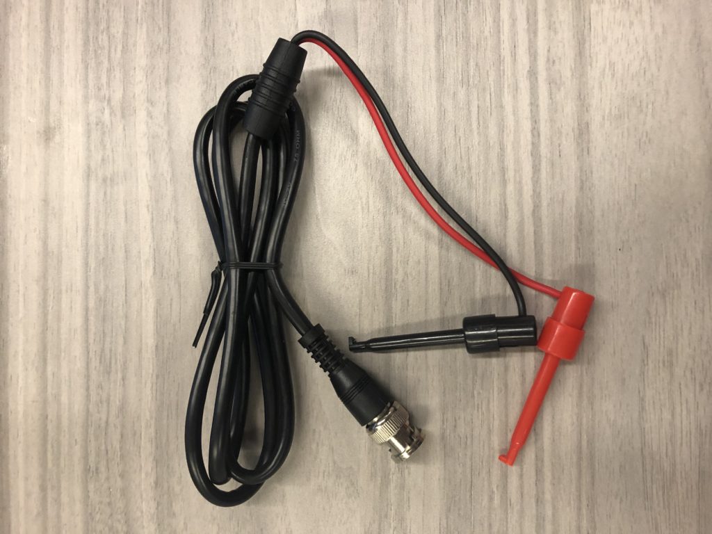
BNC connections are the industry standard for benchtop oscilloscopes utilizing coaxial cables rather than simple wires like MTE connections. BNC have a locking connection to the oscilloscope which can be really helpful if you’re moving around the circuit or your Analog Discovery Studio a lot. Unlike the MTE connections, BNC are single-ended measurements. This means that your cable probes a node in your circuit with reference to ground rather than some other node in your circuit. Oscilloscope probes that use a BNC connection generally have a wider bandwidth of operation, less noise, and consequently hold better signal integrity when compared to MTE cables. BNC oscilloscope probes generally have an attenuation switch to switch from x1 to x10. Simply put, if scoping digital circuits at high frequencies, it is usually helpful to switch to x10. The reason being that this mode of operation adds high resistance to the coaxial connection, which normally has very low resistance in combination with parasitic capacitance and inductance as a function of the length of cable. Without adding higher resistance when measuring a digital circuit, you risk transmission line reflections between the oscilloscope and your circuit, which can result in erroneous measurements or a change in how your circuit actually operates (typically in an undesirable way). BNC connections do offer other types of leads like alligator clips and banana clips in addition to typical BNC scope probes.
The engineering message is as old as time: use what’s best for your application. The great thing is that the Analog Discovery Studio gives you the option to use either cable type when using the Oscilloscope or Waveform Generator.