

Welcome back to the Digilent Blog!
There are motors everywhere in the world around us– in cars, printers, computers, washing machines, electric razors, you name it. Unfortunately, there are a lot of people (myself included up until very recently) that wouldn’t know what to do if they were handed a motor and told to run it. So I decided that I want to change that. Let’s learn to run a stepper motor!
Stepper motors are one of the three main classes of motors: the other two are DC motors and servo motors. As a brushless motor, the central shaft of a stepper motor does not physically touch anything in order to rotate. Rather, stepper motors use electromagnets that are concentrically located around the central shaft to induce it to rotate. For those of you who might not know, electromagnets work by having current flow through wire that is coiled around a “soft” magnet. This combination produces a magnetic field, inducing the central shaft to rotate so that the “teeth” of the shaft to line up with the teeth of whichever electromagnet is energized. A lot of stepper motors only have two such electromagnets that are located 90 degrees apart from each other.
%20Stepper%20Motor.png)
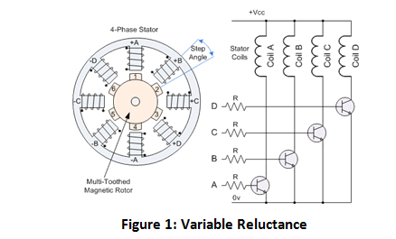
There are three main sub-types of stepper motors that are available: variable reluctance, permanent magnet, and hybrid stepper motors. A variable inductance motor purely uses the generated magnetic field to cause the central shaft to rotate. A permanent magnet stepper motor has, not surprisingly, a permanent magnet in the central shaft which will appropriately rotate to have its north and south poles line up with the electromagnet that is currently energized. Additionally, the permanent magnet stepper does not have any “teeth” on the central shaft, whereas the variable inductance motor has multiple teeth that will line up with the energized electromagnets to form a “path of least resistance”.
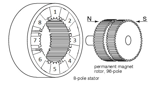
A hybrid motor is a combination of these two motors. The central shaft has two sets of teeth corresponding to the two magnetic polarities which will then rotate and appropriately line up with the teeth of the energized electromagnet. Because a hybrid stepper motor has that double row of teeth, these motors have the smallest step size and are the most popular type of motor.
But how do you actually control and run a stepper motor? There are two modes that can be used to operate a stepper motor: unipolar and bipolar mode. Unipolar mode only operates in the positive voltage range. Normally, this would mean that current could only be driven in one direction through the electromagnetic coils, producing a magnetic field in only one direction, implying that the central shaft would only be able to tilt back and forth between the two electromagnets.
This potential issue is overcome by the fact that unipolar stepper motors actually have an additional wire attached to the middle of the two coils. This allows current to flow in two different directions, from the middle to one side of the coil or to the other side of the coil. These two directions produce magnetic fields in the “opposite” directions, allowing the teeth of the magnetized central shaft rotate a full 360 degrees.
Bipolar stepper motors also have current flow in two different directions through the coils. Instead of using a central tap, they use both positive and negative (bipolar) voltage to induce the current flow in both ways through the coil. Because current is able to flow through the entire coil, instead of just half of the coil in unipolar mode, bipolar stepper motors have more torque to rotate and hold the central shaft in place.

How do you know if your stepper motor is a unipolar or a bipolar stepper motor just by looking at it? In most cases, the motor you are looking at is both. Unipolar and bipolar are just modes that you can use to run the stepper motor. The only time a stepper motor is not able to be run in either mode is when there are only four wires coming out of the stepper motor, corresponding to the both ends of the two coils and no central tap wire. If you do have more than four wires, (whether five, six, or even eight wires) at least one of those wires is a center tap wire. You can figure out which wire is which by either looking up the datasheet for your motor or measuring the resistance between two wires at a time with a multi-meter. If one particular wire always measures half of the resistance that other pairs of wires report, then you know that wire must be tapped in the middle (hence half the resistance) of a coil.

Waveform diagrams of the three main driving styles. Created by Misan2010 in the Wikimedia Commons.
Despite all of this information, we haven’t actually learned how we can run our motors. There are three main ways (yes, stepper motors do have a lot of variation) that a stepper motor can be driven. These three driving styles are full-step drive, half-step drive, and microstepping. Full-step drive always has two electromagnets (or at least two different current flows) energized at the same time. To rotate the central shaft, one of the current flows is shut off, “turning off” the electromagnet, and a different current flow is started “turning on” another electromagnet. This driving style has the most torque because two electromagnets are always energized but also has the largest step size.
The half-step drive is similar to the full-step drive, but switches between having one or two electromagnets energized. One electromagnet will start out energized and then a second one will be “turned on”. Next, the first electromagnet will be “turned off” while leaving the second electromagnet energized. A new current flow will then be started to energize the “third” electromagnet in addition to the second electromagnet being “turned on”. This driving style results in half of the step size of the full-step drive, allowing for more precision, but also results in less torque because there are not always two electromagnets that are energized.
Microstepping, as you probably suspect, has the smallest step size out of these driving styles. The way it works is by applying a variable amount of voltage to each of the coils in a sinusoidal fashion. The smaller voltage (and thus current flow) increments you are able to produce, the smaller the step size. However, this also results in a variable amount of torque that the stepper motor exhibits, depending on where you are in the step sequence.
But we are left with an important question. If we are using the stepper motor out of the chipKIT starter kit, which is rated for 5V, how do we use it with a Digilent board like the chipKIT uC32, which only operates at 3.3V?
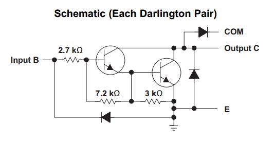
If we wanted to run the stepper motor in unipolar mode, then we need to increase the voltage output from the chipKIT uC32 from 3.3V to 5V. We could do this by using some op-amps, but I would personally rather not have to mess with all of the resistors that I would need. A Darlington transistor array, such as TI’s ULN2803, would be less messy. In a nutshell, a Darlington transistor pair has two NPN transistors arranged in such a way so that when a high logic voltage is sent from the microcontroller, the output of the transistor pair will be a low voltage (0V), drawing in current from the 5V center tapped line. However, if a low logic voltage is applied, the output will instead be at a high impedance state, because the NPN transistor will be acting as an “open circuit”. This effectively prevents any current from flowing through the IC, and so no current will flow through the coils of the stepper motor. With no current flow in the coils, no magnetic field is created so the central shaft will not move. You can learn more about how Darlington transistors work here.
For bipolar mode, we would need a way either produce a negative voltage or some way to have current flow the other direction through the entire coil, since bipolar mode requires that we do not use the center tapped wire. There is no easy way to get a negative voltage without an external power supply, but we can easily get the current flowing the other direction by using a H-bridge, such as TI’s L293D. H-bridges work by utilizing MOSFET transistors, which are able to act like a switch. These transistors are then arranged in such a way that when certain switches are “turned on”, the current will flow through the electromagnet in one direction and when a different set of switches are turned on (and the other switches are left open), the current will flow through the coils in the other direction. You can learn more about how H-bridges work from this Learn module.
If you want to work with a stepper motor of your own, a stepper motor, the Darlington transistor array, and the H-bridge are all available in the chipKIT starter kit. You can also see the little stepper motor showing off its capabilities with a full-step drive in the video below. Check it out!
Hi
thanks for the blogs about the stepper motor working principle. Its highly useful for all the industrial applications. Keep adding more blogs and share more articles.
Thank you very much for reading your article, which gave me a deeper understanding of motors.
Thanks for sharing this article about stepper motor,I am so happy to read this article,I think it’s very meaningful,which improved my learning ability and expand my knowledge aspect.
This articel topic is so creative,I learned a lot from it.Thanks for your sharing.