

This blog post discusses the concept of lock-in amplifiers and will introduce you to a newly added feature of WaveForms. The new Lock-In Amplifier feature is supported across all of our Analog Discovery devices, including the Analog Discovery 3, the original AD2, and all Pro devices.
A lock-in amplifier is an instrument that can extract small signals buried in relatively high noise. It does this by knowing the frequency of the input signal ahead of time. It typically has two inputs, one for the signal of interest and one for the signal reference. The signal must be periodic or AC, and the reference must have the same frequency. There are techniques that can convert the signal to be periodic if the signal is not periodic. In physics experiments where low levels of light are being measured, it is common to see a chopper wheel that, when spinning, turns the non-periodic light source into a periodic one.
The signal must be centered about zero free of a DC offset if the measurement is to be accurate. Some lock-in amplifiers have features that easily allow for offset correction. For instance, a high-pass filter can be used to remove DC.
After removing any DC, the AC signal is mixed with the reference frequency. Mixing is another way of saying multiplication, and it creates a new signal that is not centered about zero. The multiplication effectively squares the signal whose average (DC) value is proportional to the signal’s amplitude. If the two signals are in phase, and enough time averaging is applied, the output will be ½ of the original signal’s amplitude. The output value is proportional to the phase difference between the signal and reference. Because of this, the lock-in amplifier is also called a Phase Sensitive Detector.
The process can be described as:
Input Signal: A sin (w1t + ϴ)
Reference: sin (w2t)
Product: A sin (w1t + ϴ) sin (w2t)
Using the trigonometric identity: sin A sin B = ½ cos (A – B) – ½ cos (A + B)
The Product becomes: ½ A cos ([w1 – w2] t + ϴsig – ϴref) – ½ A cos ([w1 + w2] t + ϴsig – ϴref)
If you remove the high-frequency portion [w1 + w2] with a low-pass filter, the equation reduces further to
½ A cos ([w1 – w2] t + ϴsig – ϴref)
When w1 = w2, it reduces to:
½ A cos (ϴ), where ϴ is ϴsig – ϴref
A side effect of the mixing process is a reduced amplitude. However, the tradeoff is that noise is significantly reduced. So, how does it remove noise? It turns out that noise is just unwanted sine waves at different amplitudes and frequencies. When a frequency other than the reference is present and is mixed using the signal’s reference, it creates a new waveform whose amplitude is equally above and below zero and has a time-averaged value of zero. It is an adjustable filter whose output is locked to the reference frequency, hence the name lock-in amplifier.
The bottom trace in Figure 1 is the result when the signal is squared. The result is a waveform that is completely above zero and whose time-averaged DC value is proportional to the input signal’s amplitude. 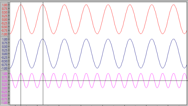
Figure 1
The time-averaged DC value changes if the input signal and reference are not in phase. The bottom trace in Figure 2 shows what happens when there is a 90º difference. It is now centered around zero with a time-averaged DC of zero. 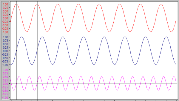
Figure 2
Figure 3 exaggerates how noise is separate from the signal of interest. As a result of the multiplication, the signal is elevated off zero; however, the noise (bottom trace) accompanying it remains centered around zero. The time average noise value is zero, leaving behind the signal’s DC value. 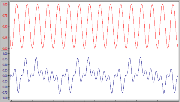
Figure 3
The Lock-In amplifier feature of Digilent’s Waveforms and an Analog Discovery 3 (AD3) can be used to test the theory. First, make a voltage divider with a 1 MΩ in series with a 1000 Ω resistor. The 1000 Ω resistor will provide a millivolt signal when the circuit is excited by a one-volt sine wave, small enough to test the Lock-In Amplifier.
Next, connect a Wavegen channel (W1) across both resistors and a Scope channel across the 1000 Ω resistor, as shown in Figure 4. 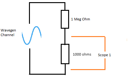
Figure 4
We want to excite the circuit with a noisy signal to show that the Lock-In Amplifier can be used to extract a signal buried in noise. If you have not done so, start Waveforms and add a Wavegen channel. Change the mode from Simple to Modulation. This will give us an instrument to output a sine wave with noise. Change the Carrier→Type to Sine, one-volt amplitude. Change the FM→Type to Noise at 2k Hz. Change the AM→Type to Noise at 10k Hz. 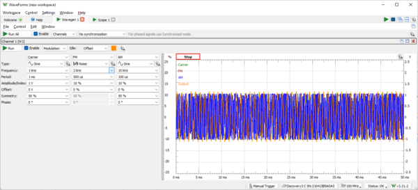
Figure 5
For this experiment, we don’t need to supply a reference signal. Instead, we can use the Lock-In’s internal reference. The WaveForms Lock-In uses a two-phase detector scheme shown in Figure 6. 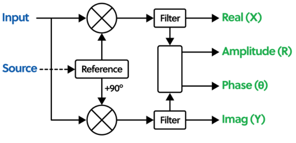
Figure 6
The input signal gets mixed with the Reference signal and 90º phase-shifted version of the reference. This produces two outputs: the in-phase (X) and quadrature component (Y). The amplitude (R) can then be found by taking the square root of the sum of the squares (X2 + Y2). This removes the requirement for the reference to be in phase with the input signal.
Next, add a Scope instrument and enable one channel to show how it works. Start both the Wavegen and the Scope. Zoom in on the oscilloscope (Scope-1) to see the input signal. The lighter shaded area is noise. The AD3 does a good job displaying the signal, but it is still challenging to determine the amplitude due to noise. 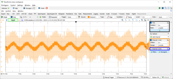
Figure 7
Next, add a Lock-In Amplifier from the Add Channel list and make the following changes.
Set the Reference to Internal
Set the Frequency to 1000 Hz to match the input signal
Set the Filter to Butterworth, 8th order low pass 500 Hz
Correct the amplitude by setting the gain to 2x 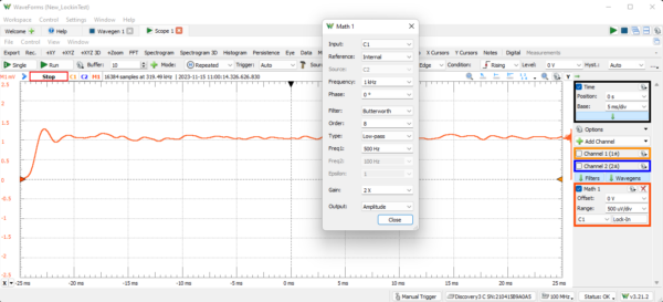
Figure 8.
Select Measurements from the Scope toolbar. On the Measurements window, click Add, and choose Math→Vertical→Average. The time-averaged measurement displays our signal amplitude, which is one millivolt. 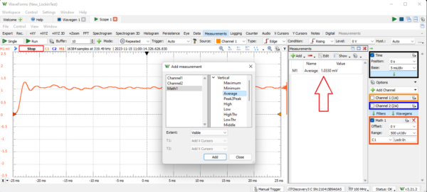
Figure 9
The AD3 Lock-In Amplifier does an excellent job of extracting our signal from the noise, but it has limitations. When measuring a small signal, normally acceptable DC offsets become more pronounced. Care must be taken to ensure that the input signal is centered on zero and that the input channel reads zero when attached to the ground.
Dynamic range is another consideration. The AD3 uses a 14-bit ADC with a resolution of 336 microvolts per count when the lower (+/- 2.5 volts) input range is selected. Our one millivolt measurement uses a fraction of its dynamic range. Of 214 counts, only a handful of A/D counts comprise the measurement. If smaller values need to be measured, consider amplification so that the measurement uses more of the dynamic range.
The Lock-In Amplifier is a demodulator and can also be used to demodulate an Amplitude Modulated (AM) signal.
Start with a new workspace. Add a Wavegen instrument and configure it for Modulation. Set the Carrier frequency to 1M Hz. Turn off the FM channel. Configure the AM channel to be a Triangle wave at 10k Hz, as shown in Figure 10. 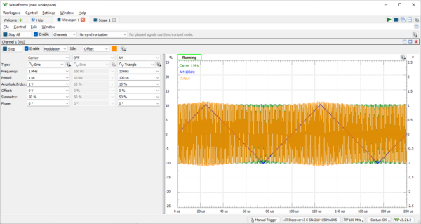
Figure 10
Add a Scope instrument and enable Scope-1. For this experiment, physically connect Scope-1 to the Wavegen channel in a loopback fashion. Start both the Wavegen Channel and the Scope. Add a Lock-In amplifier and configure it, as shown in Figure 11. 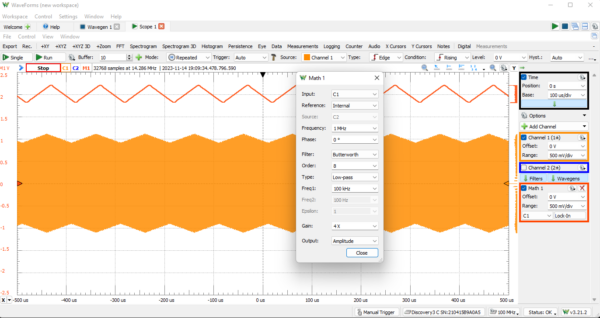
Figure 11
Add a second Math channel; instead of selecting the Lock-In Amplifier, select Simple. Set the channel on the Simple math channel to M1. Set the operation to AC, and it will extract the AC signal from the first Math channel. The 10k Hz triangle wave is extracted from the 1M Hz Carrier wave using the Lock-In Amplifier and a Simple AC math channel. 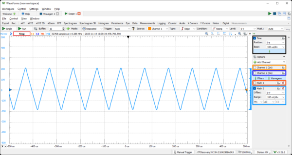
Figure 12
This one i needed years ago.
Now its basically implemented.