

In my last blog post “DIY Makey Makey using LabVIEW” I talked about how I used a WF32 and LabVIEW to recreate some of the basic functionality of a Makey Makey. While I was making this Instructable however, I started to see the potential of using this type of device with LabVIEW. I realized that you would be able to quickly create a physical interface for a VI, so I decided to try and create a simple controller for my mouse and keyboard control VI using a piece of cardboard and copper tape.
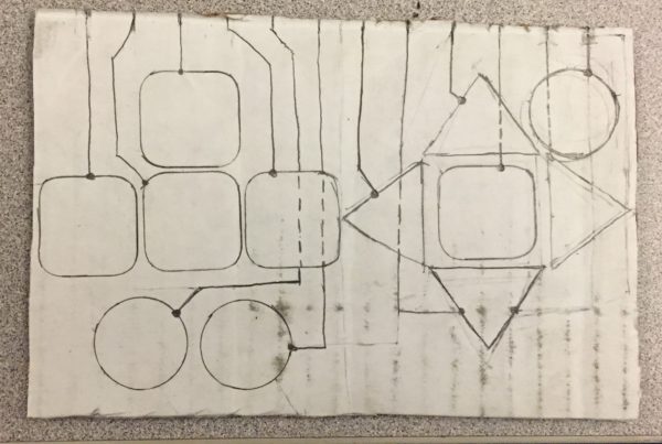
I started by drawing 12 evenly spaced lines at the top, this is where each of the gator clips will attach. Next, I cut out 12 pieces of copper tape that I used as buttons for your controller. Then I use them to set up an outline for the controller. Once I had the button placement down I outlined the paths from the 12 lines at top to each of the buttons. I used a dotted line in areas where you are having to cross over one button to get to another.
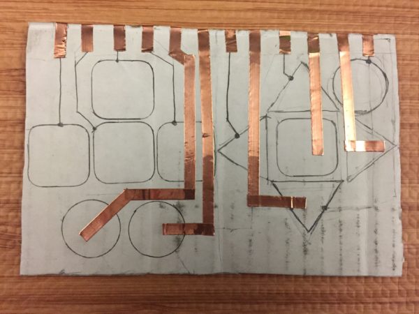
Next, I wrapped 12 shorts strips of copper tape around the top at each of the points that you marked earlier. Then I used the copper tape for all the lines that crossed over buttons.
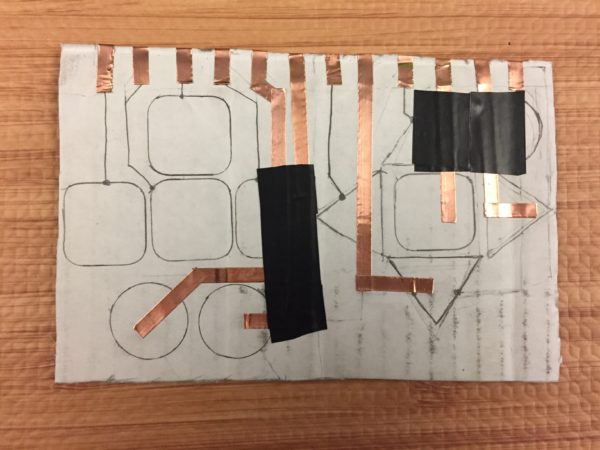
Next, I used electrical tape to cover the copper tape in all the areas that it crossed over another button. Then I outlined all the rest of the lines with copper tape.
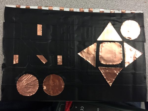
Next, tape across your controller with electrical tape starting at the bottom and moving up. Once some part of a buttons copper tape has been covered by electrical tape place more copper tape in it’s place on top of the electrical tape.
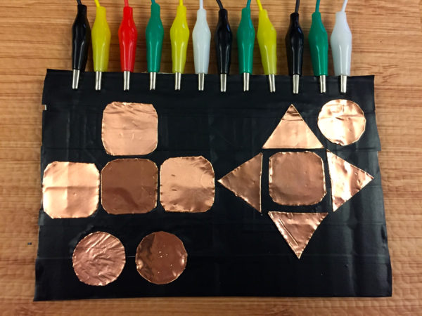
Finally, you will be able to attach all of your buttons and connect your gator clips.
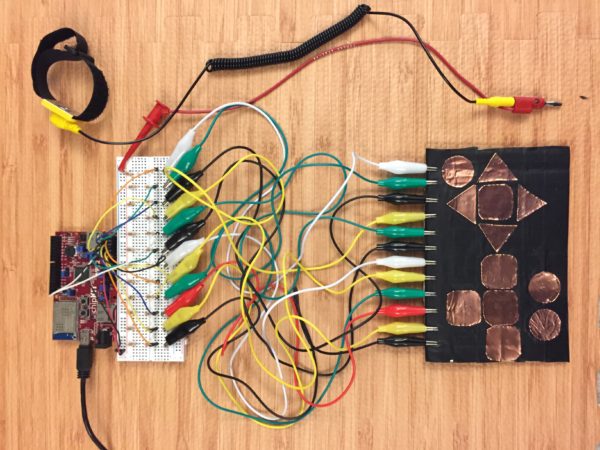
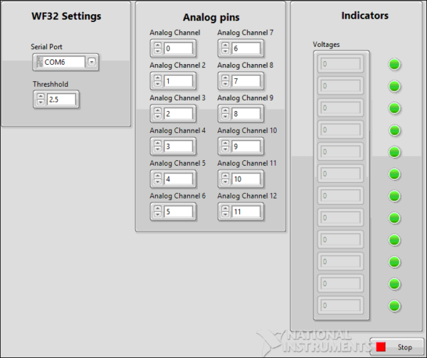
When you touch one of the buttons while watching the wristband the voltage read by its analog channel will drop significantly. By setting a threshold voltage to 2.5 volts you will be able to tell when one of the buttons has been pressed. There are many uses for this circuit, in one of my other Instructables “DIY Makey Makey using a WF32 and LabVIEW” I use LabVIEW to allow this circuit to control my computer’s keyboard and mouse. The code below is a simplified version. You can add this code to any VI and then replace boolean controls on the front panel with one of these 12 local variables.
Thank you for reading my blog post, and check out my Instructable where I provide detailed step by step instructions. If you are interested in making this project yourself but don’t have the right supplies you can purchase the LabVIEW physical computing kit with chipKIT WF32. This kit includes a copy of LabVIEW 2014 home edition, a WF32, and everything you will need to run LINX 3.0 and start making projects. Also make sure to check out the homemade Makey Makey, which is sure to provide hours of entertainment. Please comment with any questions or comments you may have.