

One of the reasons I like working at Digilent is that we are primarily an educational company. Because of that, I thought some of you might want to know how we use Digilent products in our classwork at Washington State University (WSU).
In one of my classes at school, EE352, our final project was to design an AM radio transmitter and an AM radio receiver. Since we were in teams of two, we used two Analog Parts Kits for our design, however with some more resistor calculations you could complete the design with one parts kit. I decided to be lazy and use potentiometers for all of my resistors. That way I could have custom resistor values, without having to do any calculations.
Here is a video of the results:
In the video, I’m adjusting the message signal input on the bottom left on the waveform generator. On the top right you can see the output of the receiver on the oscilloscope, and you can hear what the wave sounds like. I chose to put the speaker from the Analog Parts Kit in the receiver so I needed to output a square wave. This is the equipment that I was using in lab, but you can replace the oscilloscope and waveform generator with the Analog Discovery or the EE Board. For our purposes we modeled the radio antenna by passing the AM signal through a BNC cable. In the video you can hear some noise for certain frequencies. Unfortunately our design wasn’t perfect, but it gave us lots to talk about in the conclusion and recommendations section of our report.
It’s pretty neat what you could potentially do with the Analog Parts Kit and Analog Discovery. Now that you’ve seen the cool result, maybe you’d like to know some of the theory.
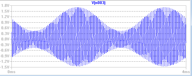
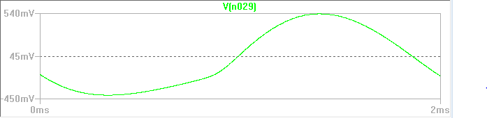
AM radios transmit and receive AM radio waves, such as the one shown in the image below. The AM wave is made up of two separate signals, the carrier wave and the message signal. The message signal carries the information that you want to send. For this implementation, the message signal is produced by the oscilloscope and is received and turned into sound. The carrier wave is much higher energy and is there to make sure the message signal makes it from the transmitter to the receiver.
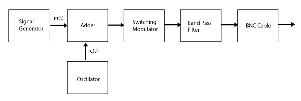
The transmitter takes uses an oscillator to create the carrier signal from noise, and a message signal from the signal generator, and creates the AM wave in a series of steps. Each step is shown in the block diagram.
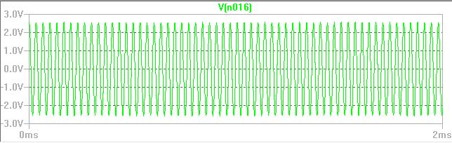
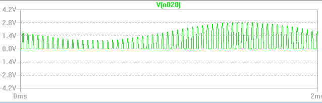
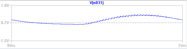
The oscillator takes noise from the environment and amplifies it to create a carrier wave with frequency 30kHz, shown below.
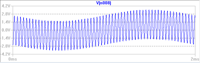
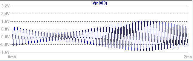
The adder then adds the message signal to the carrier signal. You can see the message signal in the outside shape of the wave, also known as the envelope, and you can see the carrier signal in the high frequency oscillations within the lower frequency message signal.
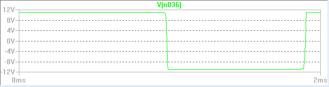
The switching modulator takes advantage of the properties of a diode to only pass the positive half of the signal from the adder. Ideally diodes only pass current in one direction.
The band pass filter filters out all frequencies outside of a certain range. A band pass filter has a specified gain for frequencies that it allows to pass and a very small gain for frequencies it doesn’t pass. Gain is the output amplitude divided by the input amplitude. For example, if you wanted an 8V amplitude sine wave and had an input of a 4V sine wave, you would need a gain of 2.
Here is the completed transmitter:
The receiver takes the AM wave and breaks it back down into just the message signal. A reciever could be built out of just the first three blocks in the block diagram below, but we wanted to hear the received signal, so we added the last two and connected that output to a speaker.
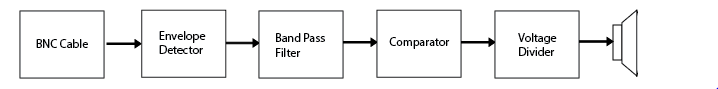
The envelope detector takes the envelope of the AM signal. The envelope is what you would get if you traced the outside edge of the AM wave. This is primarily made up of the message signal.
The band pass filter takes out all of that extra noise on the envelope detector to get back to a version of the message signal with a smaller amplitude.
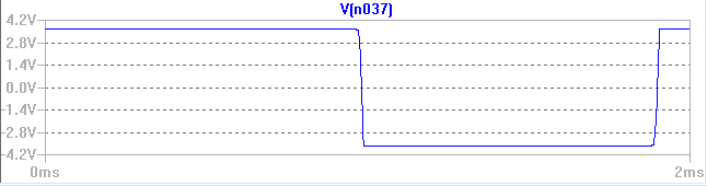
The comparator takes the frequency of the input sinusoidal signal, and makes it into a square wave with an amplitude, the same as the voltage supplied to the op amp that’s used.
Our speakers can only handle a peak to peak square wave of 8V so we used a voltage divider to divide that amplitude.
Here is the completed reciever:
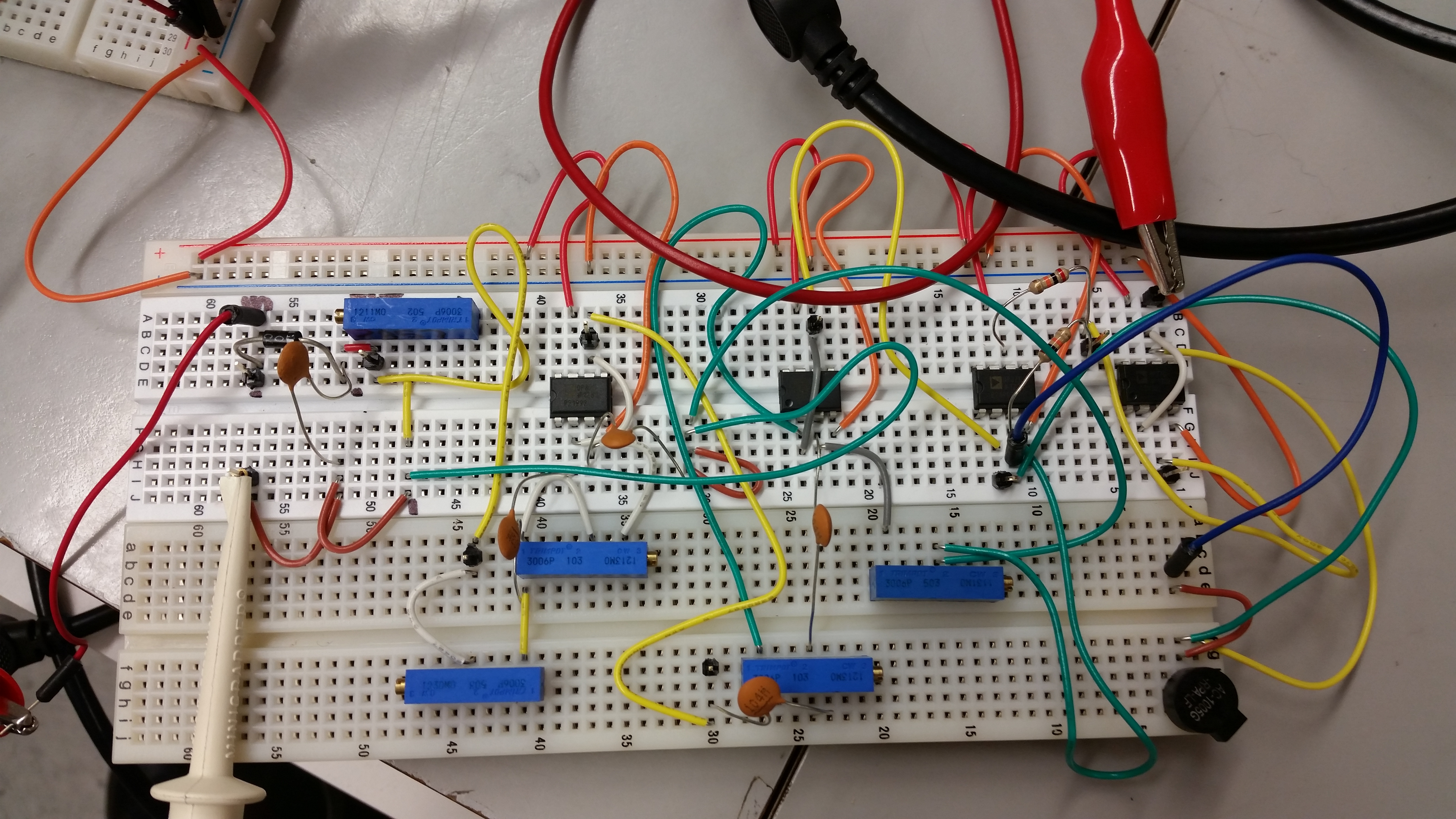
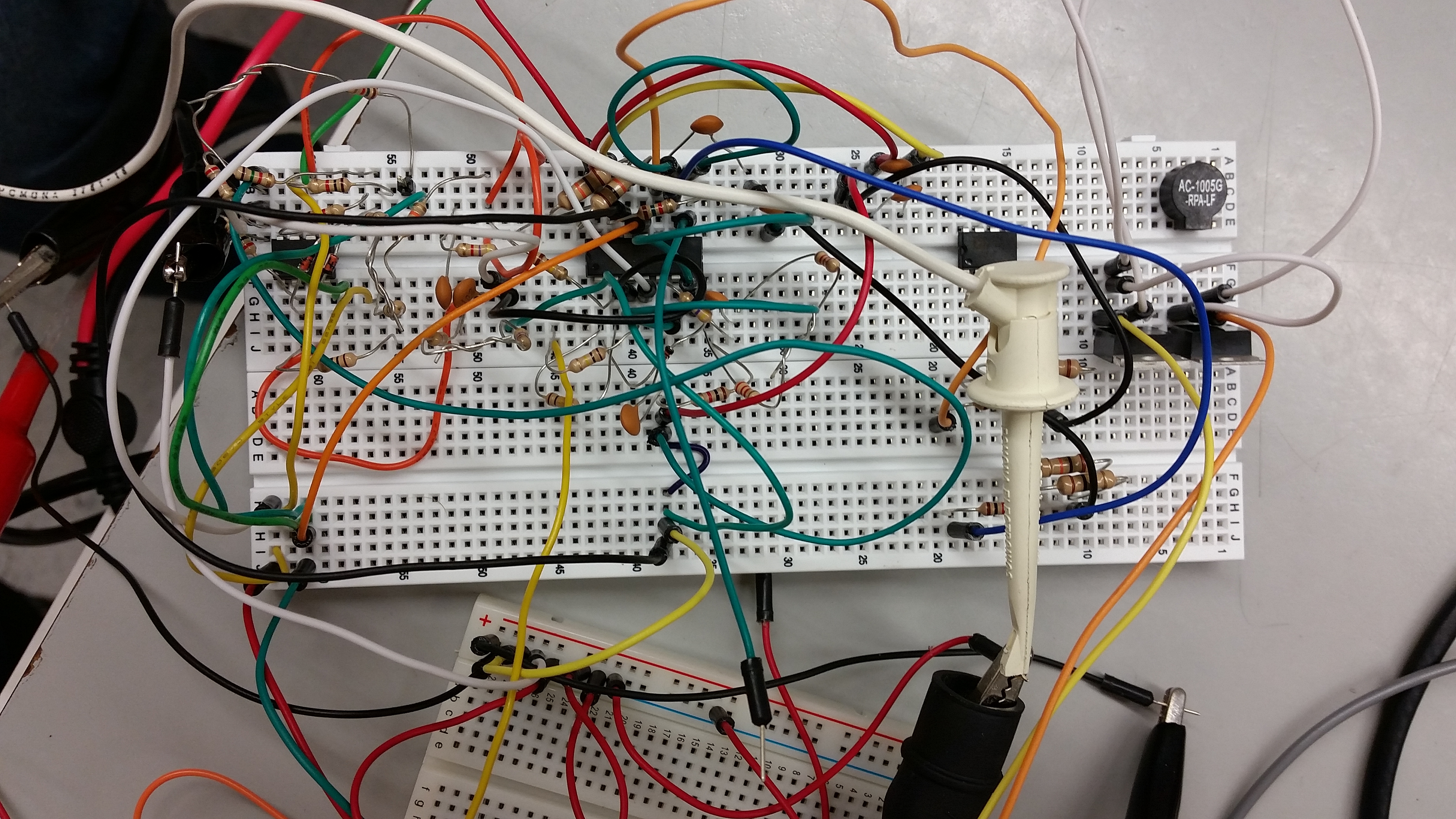
Below is a schematic of the actual circuit that we implemented. You can see each section of both the transmitter and receiver labeled.

If you thought that project in analog circuits was cool, check out our other projects at learn.blog.digilentinc.com.
Kaitlyn, very well documented and written post.
Thank you so much for sharing it.