

So let’s say you have been working on a complex LabVIEW VI, you finally finish, and you go to test it, but it doesn’t work. You go back to try and correct the problem but are overwhelmed by the mess of wires and blocks. So many while loops and case structures, that it’s actually bigger than your screen size, so you have to use the scrollbars to navigate the program. This is the perfect situation to start creating SubVI’s!
SubVIs are the same as VIs, they contain front panels and block diagrams, but you call them from within a VI. A SubVI is similar to a subroutine in text-based programming languages.
So, what exactly is a SubVI? It is a VI that is placed on the block diagram of a higher-level VI. It allows you to write modules of code that you can wire into your diagrams later. The icon is what the SubVI will look like on another VI’s block diagram. The connector pane allows you to assign terminals on the icon to front panel controls and indicators for the purpose of wiring values into and out of a SubVI.
Creating a SubVI from an Existing VI:
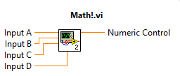
You can simplify the block diagram of a VI by converting sections of the block diagram into SubVIs. Create a new VI and construct the following block diagram.

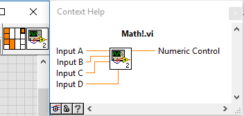
Next, Select the section of the block diagram you want to convert and then select Edit»Create SubVI from the Tools menu. The selected section of the block diagram is replaced with an icon for the SubVI. LabVIEW creates controls and indicators for the new SubVI, automatically configures the connector pane based on the number of control and indicator terminals you selected, and wires the SubVI to the existing wires. The SubVI interface (icon and connector pane) is not as immediately obvious as the front panel and block diagram when a VI is opened. It is accessible from the upper right-hand corner of the front panel window.
Now that the connector pane is wired for this VI, it is a usable SubVI. However, to make it easily identifiable in the block diagrams of VIs that call it, you should give it a custom icon. This is not necessary, but a brief summary of the steps to do so are detailed below:
First, use the right click menu on the Icon or Connector Pane to select “Edit Icon.” The following utility appears:
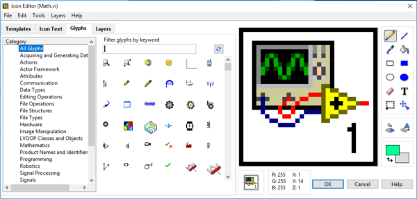
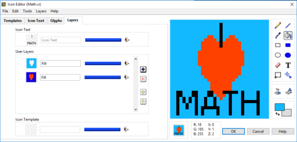
This program operates more or less like a rudimentary paint program. I made the following simple icon for this example (the heart took way longer than I thought it would, I must really like math….).
But what if you want to reuse this SubVI in another VI? First, save the SubVI. Then open the other VI, right click the block diagram, and click “Select a VI…”. This then brings up a file browser, then browse to the SubVI you saved and double click it. This drops the SubVI in the block diagram with it focused on your mouse so you can drag it around the new VI, then click to drop it. You now have your SubVI on your Front Panel!

Thank you for reading my blog post, and for more information about creating SubVI’s in LabVIEW check out this link. If you are interested in trying out LabVIEW for yourself, you can purchase a copy of LabVIEW 2014 Home Edition which includes everything you will need to run LINX 3.0. Please comment below with any questions or comments you may have.