

The Question
A user getting started with the Analog Discovery 3 (AD3) wanted to generate a waveform using the Arbitrary Waveform Generator while simultaneously sampling an analog input – both synchronized in time using a software trigger.
While the triggers appeared coincident when viewed on an external oscilloscope, the captured analog input data told a different story. The waveform didn’t appear at the start of the sample buffer. Instead, it showed up roughly halfway through a 12,500‑sample acquisition.
With both Analog Out and Analog In configured for software triggering, the user couldn’t find anything in the WaveForms SDK or reference documentation explaining this behavior.
The Answer
The key detail comes down to how trigger position is defined for Analog In acquisitions when using the WaveForms SDK.
Unlike what many users expect from a programming perspective, a trigger position of 0.0 does not place the trigger at the beginning of the data buffer. Instead, the trigger position is defined relative to the center of the acquisition buffer, similar to how a traditional oscilloscope works.
That means:
- A trigger position of
0.0places the trigger in the middle of the buffer - The first half of the buffer contains pre‑trigger samples
- The second half contains post‑trigger samples
So if a waveform appears around the midpoint of the buffer, the trigger is behaving exactly as designed.
To shift the trigger to the beginning of the buffer, the trigger position must be explicitly set based on the buffer size and sample rate, rather than assuming index 0 corresponds to the trigger event.
Why This Makes More Sense in WaveForms
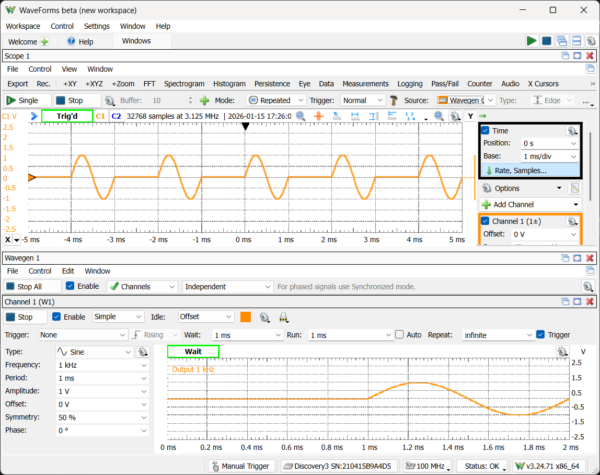
This trigger behavior is easier to visualize in the WaveForms desktop application. In the Scope instrument:
- Time Position directly corresponds to trigger position
- The trigger marker shows where the trigger falls within the acquisition window
- Sample index 0 typically represents time before the trigger, not the trigger itself
Understanding this mapping makes it much easier to translate between what you see in WaveForms and how captured data appears in the SDK.
The Result
Once the trigger position was configured with this behavior in mind, the acquisition aligned as expected and the issue was resolved.
Takeaway
When synchronizing Analog Out and Analog In on the Analog Discovery 3 using the WaveForms SDK, remember:
- The trigger position is relative to the center of the acquisition buffer
- A trigger position of
0.0does not mean “start at sample 0” - Seeing data appear halfway through a buffer often indicates correct triggering, not a timing issue
If your data looks offset, the fix may be as simple as adjusting trigger position, not your timing or wiring.
Read the full forum thread HERE