

Seven-segment displays are a classic tool in digital electronics, used to show numerical data in everything from clocks to calculators. At Digilent, we like to integrate these displays into our education-focused FPGA development boards, including the Nexys A7 and Basys 3. These displays are relatively simple to use but designing a controller for one is still complex enough to require students to build some understanding and knowledge. This makes them ideal for both learning and teaching digital design.
What is an LED?
Light-emitting diodes are one of the most foundational circuit components out there. Simply put, they have anode and cathode pins, and when a high enough voltage differential is applied across those pins, the diode emits light. For the purposes of simple digital logic, most of what you need to know is: as long as the anode has a logic “high” voltage applied to it, and the cathode is grounded or at a logic “low”, the LED will visibly glow.
What Is a 7-Segment Display?
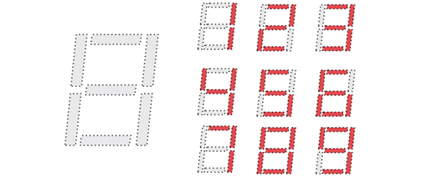
A 7-segment display consists of seven LEDs arranged in a figure-eight pattern. Each segment is labeled A through G, and when illuminated in specific combinations, they form digits (0–9) and letters (A–F). Some displays also include an eighth segment for the decimal point (DP).
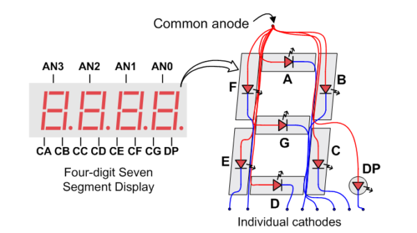
Displays often include multiple digits to represent numbers larger than the standard zero through nine a single digit offers. Seven or eight pins per digit is a lot of wires to connect to a controller chip with a potentially limited number of I/O pins, like the FPGAs used on these boards, so, some clever tricks are used to reduce the pin count. To introduce some additional terminology:
- Common Anode (CA): The anodes of each of a digit’s LEDs are connected together; segments are lit by grounding their cathodes.
- Common Cathode (CC): The cathodes of each of a digit’s LEDs are connected together; segments are lit by applying voltage to their anodes.
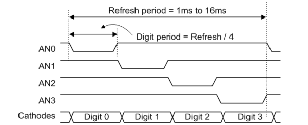
It’s also important to know that LEDs don’t turn on or off immediately – an LED that is toggled on and off will still appear to be fully illuminated as long as the refresh rate (the frequency of the toggling) is faster than the human eye’s ability to perceive the flicker.
Clever trick time – by having a single anode pin per digit and the cathode pins of each type of segment, the A’s, B’s, C’s, etc, shared by all digits, we can select which digit to illuminate by setting the anodes, and set the number to display on that digit by setting the cathodes. We can then rapidly count across the digits, displaying different numbers on each, keeping the entire display up to date, as far as the human eye is concerned.
Pin-wise, this is so much more efficient than the naive approach. For a four-digit display, instead of 28 or 32 individual signals wired to each individual LED, we’re getting away with 11 or 12 – four for the digits’ shared anodes, seven or eight for the cathodes.
How Digilent Boards Use 7-Segment Displays
Nexys A7 and Basys 3
As described above, the Nexys A7 features an 8-digit 7-segment display, controlled using time-domain multiplexing. Although only one digit is lit at a time, the display cycles through all digits rapidly, faster than the human eye can perceive, creating the illusion that all digits are lit simultaneously.
The Basys 3, also an AMD Artix™ 7 –based FPGA board intended for engineering education, similarly features a 4-digit 7-segment display.
For both of these boards, each digit has:
- A common anode pin to enable the digit.
- Cathode pins (CA–CG, DP) to control individual segments.
To display a decimal value, or even a hexadecimal value like 0x85ECA921 or 0xDEADBEEF, the FPGA cycles through each digit, enabling that digit’s anode and setting the appropriate cathode signals based on the desired character. This is managed in a Verilog or VHDL design using a counter to iterate over the digits, decoder to convert the count to common anode signals, multiplexer to select a digit based on the count, and look-up table to convert the digit’s binary data to cathode signals for display.
While displayed data can come from whatever source you might like – some Digilent demos use these displays to show PS/2 scan codes received from a connected USB keyboard – one ideal project for learners to tackle is a binary-coded-decimal (BCD) counter.
Arty Z7 + Pmod SSD
AMD Zynq™ 7000 System-on-Chip boards are also interesting learning platforms, as they feature built-in ARM processors, making them ideal for learning how CPUs can interface with custom hardware. While the Arty Z7, for one example, doesn’t include a built-in 7-segment display, it supports external modules like the Pmod SSD, which can be connected via Pmod ports. This allows users to implement similar display logic using the Zynq™ 7000 SoC’s programmable logic.
Educational Applications
Educators can use Digilent boards to teach:
- State machine design
- Combinatorial and synchronous logic
- Time domain multiplexing
- Hierarchical or modular design
- Verilog or VHDL programming
Even for those already in the professional world, displays provide easy-to-integrate ways to provide feedback to users and developers trying to debug their own systems alike.
Tips for Getting Started
- Use Digilent’s reference manuals for pin mappings and electrical characteristics.
- Start with Digilent’s example projects and demos in Vivado.
- Experiment with modifying the design to display different patterns or messages.
You’ll find plenty of useful materials on Digilent’s Reference site: https://digilent.com/reference/programmable-logic/start.
Whether you’re an educator, student, or engineer, Digilent’s FPGA boards offer a hands-on way to explore how 7-segment displays work. From simple digit rendering to dynamic animations (did somebody say snake?), these displays are a gateway to understanding digital logic and embedded design.