Table of Contents
Using External Triggers
Introduction
This guide explores the use of external triggers for use with various WaveForms tools. Note that there are many applications and approaches to using external triggers beyond what will be covered in this guide.
Inventory
- A Digilent Test & Measurement Device with Analog and/or Digital Input and Output Channels, and External Trigger Capabilities:
- MTE Cables, BNC Oscilloscope Probes, and/or BNC to Minigrabber Clip Cables, depending on the device you are using.
- A Computer with WaveForms Installed
- Installers for each supported operating system (Windows, Mac, and Linux) can be found here: WaveForms installers.
Before discussing any examples, it is important to understand what a trigger is and why a trigger is helpful. The following sections will define triggers as an acquisition tool and describe what triggers do to make signal analysis more effective.
1. What is a Trigger?
What is a trigger? How is one set up?
- Click Here to Learn the Answer
-
- Trigger: A trigger is an event that occurs with respect to a signal, that defines the window of time where an instrument captures data. A trigger can be defined in a variety of ways, but, as an example, a trigger could be the rising edge of an incoming signal, informing the instrument that you want to view the period of time around that edge, both before and after, to check the noise in the signal.
- Trigger Systems: A trigger system works with an oscilloscope, logic analyzer, or other acquisition instruments that are concerned with capturing voltage levels over time. The trigger tells the instrument what data it needs to be concerned with capturing and how to display it for the user. This is done by either pre-defined default settings, user-defined parameters, or user-defined events for the trigger to “look for” in the voltage data collected by the acquisition process over some time period. These triggers can be simple in nature or very complex depending on the application.
- Trigger Types: There are many different types of triggers, all having their own strengths, depending on the application, and influence what kind of settings or events the trigger is set to detect. The most common type of trigger is an Edge Trigger (which is commonly used with the WaveForms Scope tool) and will be the focus of this introduction to triggers. An edge trigger point is defined by (1) some voltage level and (2) if that level occurs in the input waveform on a rising edge, falling edge, or either. Waveforms has default settings for these triggers that can also be adjusted by the user. For example, a trigger point may be set to “when the signal rises above 500mV.”
- Trigger Modes: There are a few different modes that a trigger can operate under and these modes determine if the oscilloscope will display a waveform if a trigger is not detected. This tutorial covers “normal” and “auto” modes. In normal mode, the acquisition tool only collects voltage data over some time period (also called a sweep) if the input signal satisfies the trigger definition. Otherwise, the acquisition tool will either display a blank screen or remain static displaying the last acquisition. In auto mode, the acquisition tool sweeps with or without a trigger and uses a timer to sweep if there is no input signal.
- Trigger Holdoff: Trigger holdoff is an adjustable time period in which the acquisition instrument cannot generate a trigger. This can be very helpful with complex waveforms that might have multiple points that satisfy the trigger conditions within the desired acquisition data set allowing the trigger to properly display the waveform as needed.
2. How and Why Are Triggers Used?
Once set up, what does the trigger do to incoming data? How does this help the user?
- Click Here to Learn the Answer
-
Triggers act like a comparator. With default settings or a user-defined voltage level and slope (rising edge, falling edge, or either), when the input to the trigger system matches these settings, the trigger system sends a pulse to its output. This pulse is monitored by the acquisition instrument and another sub-system called a time-based interpolator.
When the acquisition instrument sees this pulse from the trigger system, it begins to digitize, process, store, and measure this data. Before this waveform data can be displayed on the screen, the time-based interpolator figures out what address in the waveform buffer matches the defined trigger point and tells the acquisition instrument to display this data at time t=0.0 seconds.
By repeatedly displaying similar sections of the input signal at a specified trigger point, a trigger helps display a dynamic waveform as a static image. Otherwise, the waveform would just race across the display in a way that would be hard to interpret and impossible to take measurements with.
Triggers can also be helpful for capturing data around or locating an infrequent event. Some examples include digital pulses that are: missing, irregular in width, or not reaching valid logic high or low levels.
3. What is an External Trigger?
What makes a trigger “external”?
- Click Here to Learn the Answer
- An external trigger functions the same as any other trigger, such as those in WaveForms' Scope instrument. However, an external trigger uses a signal external to the acquisition tool to generate a trigger. Note that the signal does not need to be connected to a scope channel and thereby take up valuable data throughput. This external signal can be generated by another acquisition tool, circuit, or device set up to provide the appropriate signal to the external trigger input at the appropriate time.
4. Examples using External Triggers
Below are a few examples of applications using an external trigger. These are not the only uses for external triggers but merely a showcase of how an external trigger might be used in practice and to allude to further applications. Two examples are presented:
4.1 Oscilloscope External Trigger
This is an example of using an analog signal to trigger the oscilloscope. Once set up, when pushed, the button in this example will generate a trigger.
4.1.1 Hardware Setup
|
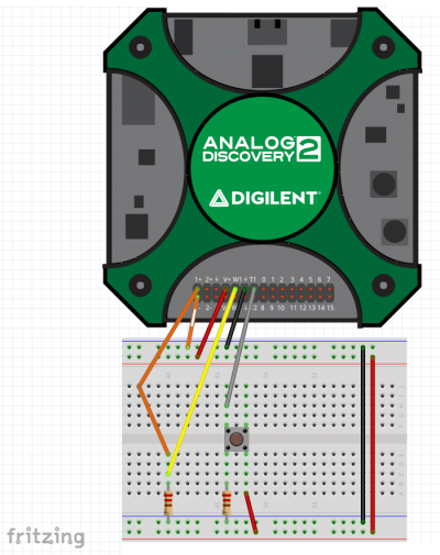
Set up the following hardware as shown in the schematic and diagram to the right. Trig 1 refers to the External Trigger 1 pin on the Digilent Test and Measurement Device. The resistors are for limiting the current into and out of the WaveGen, Scope, and Trigger pins. While a push button was used, its behavior could be emulated by connecting and disconnecting a resistor or jumper wire. Components:
See the dropdowns below for additional figures of the circuit setup, with BNC and MTE cables. Note: If using BNC cables for analog input, refer to the Using the Oscilloscope guide for additional information on setup, including selecting an attenuation factor in the WaveForms application. |
|
|

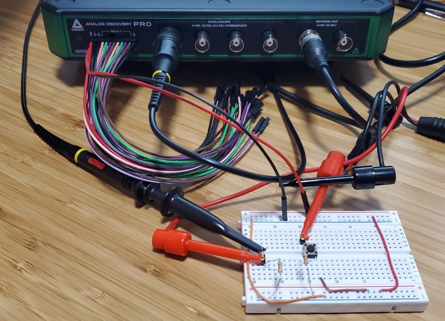
- Hardware Setup: BNC Cables
-

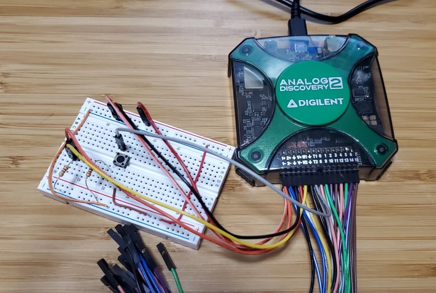
- Hardware Setup: MTE Cables
-

4.1.2 Software Setup
This software setup section is streamlined to focus on the external trigger application. For more detailed help with any of the following WaveForms instruments, refer to their “Using” guides, linked below.
Note: In order to show each of the opened instruments on the screen at once, click on the Docking Windows button ( ) at the top right corner of the window. To return to the default tabbed view later, click on the Tabbed Windows button (
 ) adjacent to the Docking Windows button.
- Open the WaveGen instrument and keep it at default settings (1V at 1kHz)
- Open the Scope instrument and make the following adjustments in the Control Bar
- Change the Trigger Type drop-down menu from “Auto” to “Normal”
- Change the Source drop-down menu from “Channel 1” to “Trigger 1”
- Open the Supplies instrument, change the Positive Supply to 3.3V, and disable the Negative Supply (if present)
- Click the green “Run” arrow on all three WaveForms instruments
Refer to the image to the right to see what the workspace will look like after setup is complete.

4.1.3 Scope External Trigger Operation
Once the hardware and software are set up properly, pushing down on the pushbutton will send 3.3V to the External Trigger 1 pin, generating a trigger for acquisition. The trigger point should change each time the button is pressed since no condition is set to be displayed at t=0.0 seconds and the WaveGen is constantly running. The sine wave should be displayed statically in the Scope plot plane and update with every push of the button.

4.2 Logic Analyzer External Trigger
This is an example of using a digital signal to trigger the logic analyzer. A clock signal from a DIO pin is used to periodically generate a trigger.
4.2.1 Hardware Setup
The hardware used in this example is a simple loopback circuit. Digital input/output pins will be used to stimulate the external trigger and to provide some data to be read.
Connect the External Trigger 1 to the DIO0 pin.
DIO1 will also be used, but since Digilent Test and Measurement devices support capturing the state of a digital output pin as if it was a digital input, it will not be connected to anything.
These connections are detailed in the diagram to the right.

4.2.2 Software Setup
The following software setup is streamlined to focus on the External Trigger application. For more detailed help with the following instruments, refer to their “Using” guides, linked below.
Note: In order to show each of the opened instruments on the screen at once, click on the Docking Windows button () at the top right corner of the window. To return to the default tabbed view later, click on the Tabbed Windows button () adjacent to the Docking Windows button.
- Open the Patterns instrument and do the following:
- Add Signals DIO0 and DIO1
- Change DIO0 type to “Clock” and Parameter 1 to “500mHz
- Change DIO1 type to “Random” and Parameter 1 to “10kHz””
- Open the Logic instrument and do the following:
- Add Signals DIO0 and DIO1
- In the Control Bar, change the trigger Type drop-down menu to “Normal” and the trigger Source drop-down menu to “External 1”
- Click the green “Run” arrow on each instrument
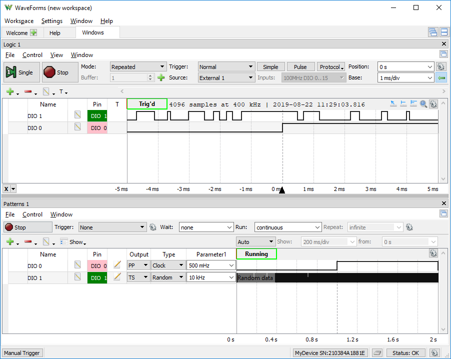
Refer the image to the right to see what the workspace will look like after setup is complete.
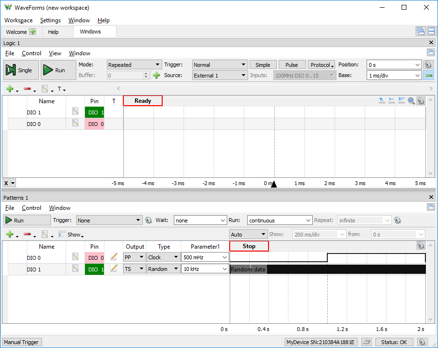
4.2.3 Logic External Trigger Operation
Viewing the Logic instrument, the Patterns instrument is generating a clock signal with a two-second period on DIO0 which is being sent to the External Trigger 1 pin. When DIO0 is driven to a logic high level, a trigger is generated.
The Patterns instrument is generating a random logic signal at a rate of 10kHz on DIO1 which is being observed in the Logic instrument on the respective DIO1 signal line. DIO1 should update every two seconds in the Logic instrument with every rising edge of the clock signal from DIO0 being sent to the External Trigger 1 pin.
Note: This is not a manually operated trigger whereas the previous example is.
Next Steps
More examples of External Triggering being used are covered in the Using Cross Triggering guide
For more guides on how to use the Digilent Test and Measurement Device, return to the device's Resource Center, linked from the Test and Measurement (Redirect) page of this wiki.
For more information on WaveForms visit the WaveForms Reference Manual.
For technical support, please visit the Test and Measurement section of the Digilent Forums.