Table of Contents
Using Cross Triggering
Introduction
When using Test and Measurement devices, understanding “triggering” - when and why data is acquired - is important. This guide introduces triggering as a concept, then explores several approaches to cross-triggering between multiple instruments and devices within the context of the WaveForms application.
Note: While the examples of cross triggering presented here primarily use Analog Inputs and Outputs, the same concepts can be applied to Digital I/O, or a mix of both Analog and Digital.
Inventory
Dual Mode
Since this guide was created, the Dual Mode feature of WaveForms was introduced, which allows multiple devices to be connected via their trigger pins to double the channel count of the combined MSO system. Not all WaveForms-compatible devices support Dual Mode. More information can be found in this blog post: Extending Channel Counts by Using Dual Mode.
- One or more Digilent Test & Measurement Devices with Analog I/O and/or Digital I/O:
- MTE Cables, BNC Oscilloscope Probes, and/or BNC to Minigrabber Clip Cables, depending on the device you are using.
- A Computer with WaveForms Installed
Before discussing any examples, it is important to understand what a trigger is and why a trigger is helpful. The following sections will define triggers as an acquisition tool and describe what triggers do to make signal analysis more effective.
1. What is a Trigger?
What is a trigger? How is one set up?
- Click Here to Learn the Answer
-
- Trigger: A trigger is an event that occurs with respect to a signal, that defines the window of time where an instrument captures data. A trigger can be defined in a variety of ways, but, as an example, a trigger could be the rising edge of an incoming signal, informing the instrument that you want to view the period of time around that edge, both before and after, to check the noise in the signal.
- Trigger Systems: A trigger system works with an oscilloscope, logic analyzer, or other acquisition instrument that is concerned with capturing voltage levels over time. The trigger tells the instrument what data it needs to be concerned with capturing and how to display it for the user. This is done by either pre-defined default settings, user defined parameters, or user defined events for the trigger to “look for” in the voltage data collected by the acquisition process over some time period. These triggers can be simple in nature or very complex depending on the application.
- Trigger Types: There are many different types of triggers, all having their own strengths, depending on application, and influence what kind of settings or events the trigger is set to detect. The most common type of trigger is an Edge Trigger (which is commonly used with the WaveForms Scope tool) and will be the focus of this introduction to triggers. An edge trigger point is defined by (1) some voltage level and (2) if that level occurs in the input waveform on a rising edge, falling edge, or either. Waveforms has default settings for these triggers that can also be adjusted by the user. For example, a trigger point may be set to “500mV on a rising edge.”
- Trigger Modes: There are a few different modes that a trigger can operate under and these modes determine if the oscilloscope will display a waveform if a trigger is not detected. This tutorial covers “normal” and “auto” modes. In normal mode, the acquisition tool only collects voltage data over some time period (also called a sweep) if the input signal satisfies the trigger definition. Otherwise, the acquisition tool will either display a blank screen or remain static displaying the last acquisition. In auto mode, the acquisition tool sweeps with or without a trigger and uses a timer to sweep if there is no input signal.
- Trigger Holdoff: Trigger holdoff is an adjustable time period in which the acquisition instrument cannot generate a trigger. This can be very helpful with complex waveforms that might have multiple points that satisfy the trigger conditions within the desired acquisition data set allowing the trigger to properly display the waveform as needed.
2. How and Why Are Triggers Used?
Once set up, what does the trigger do to incoming data? How does this help the user?
- Click Here to Learn the Answer
-
Triggers act like a comparator. With default settings or a user defined voltage level and slope (rising edge, falling edge, or either), when the input to the trigger system matches these settings, the trigger system sends a pulse to its output. This pulse is monitored by the acquisition instrument and another sub-system called a time-based interpolator.
When the acquisition instrument sees this pulse from the trigger system, it begins to digitize, process, store, and measure this data. Before this waveform data can be displayed on the screen, the time-based interpolator figures out what address in the waveform buffer matches the defined trigger point and tells the acquisition instrument to display this data at time t=0.0 seconds.
By repeatedly displaying similar sections of the input signal at a specified trigger point, a trigger helps display a dynamic waveform as a static image. Otherwise, the waveform would just race across the display in a way that would be hard to interpret and impossible to take measurements with.
Triggers can also be helpful for capturing data around or locating an infrequent event. Some examples include digital pulses that are: missing, irregular in width, or not reaching valid logic high or low levels.
3. What is Cross Triggering?
What makes a trigger a “cross”-trigger?
- Click Here to Learn the Answer
-
In the general sense, cross triggering describes systems where multiple instruments - often different devices - share trigger events. This can mean that either both instruments capture the signal containing the trigger event, or that when one of the instruments detects the trigger event, it generates a signal to trigger the other instrument.
Since benchtop oscilloscopes traditionally only contain one instrument, cross triggering typically refers to sharing the same trigger between multiple devices. Because Digilent's Test and Measurement devices contain many different instruments, this guide covers both the multiple-device case and cross triggering between multiple virtual instruments within the same device.
4. Examples of Cross Triggering Systems
Two examples of systems using cross triggering are presented here:
4.1 Cross Triggering between Instruments
This example demonstrates how using cross triggering makes it easier to change trigger sources across multiple instruments on a single device. A loopback circuit will be created that will connect the device's analog output to its analog inputs. We will experiment with several different trigger configurations, shared by both the device's Scope and Wavegen instruments, to do single-shot captures of an input waveform.

Note: You will see several photos of hardware in use throughout this guide. Whether or not your device shows up, rest assured, the concepts presented here are applicable to any WaveForms-compatible Digilent Test and Measurement device.
4.1.1 Hardware Setup
Connect the Digilent Test and Measurement device to the host computer.
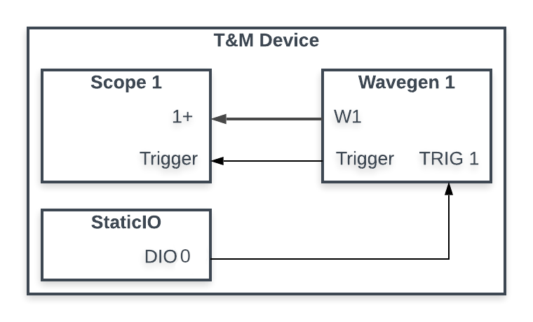
Connect the analog input channel 1 positive pin (1+, orange cable) to the waveform generator output channel 1 pin (W1, yellow cable). Then connect the analog input channel 1 negative pin (1-, orange and white cable) to ground (down arrow, black cable). Lastly, connect the external trigger 1 pin (TRIG 1, grey cable) to the digital input/output pin 0 (DIO 0, pink cable).
The circuit achieved by these connections is a simple loopback, allowing the Test and Measurement device's waveform generator to provide a stimulus for its own oscilloscope, and to generate an external trigger with its digital I/O. See the block diagram to the right for a visual representation of how triggers and data flow through the system.
4.1.2 Software Setup
The following software setup is streamlined to focus on the application of the triggers. For more detailed help with the following instruments, refer to their “Using” guides, linked below.
Launch WaveForms, then open the following instruments:
- Open a new Wavegen instrument, then make the following changes to its configuration:
- Set the Channel Synchronization to Independent
- Set the Trigger source to Manual
- Set the Wait time to none
- Set the Run time to 1 ms
- Set the Repeat count to infinite
- Leave all other settings as their defaults
- Open a new Scope instrument, then make the following changes to its configuration:
- Set the Trigger Mode to Repeated and Normal
- Set the Trigger Source to Wavegen C1
- Ensure the Time Position is 0 s
- Set the Time Base to 1 ms/div
- Ensure Channel 1's Offset is 0 V
- Ensure Channel 1's Range is 500 mV/div
- Disable the unused channels by unchecking their box
- Open a new StaticIO instrument, then make the following change to its configuration:
- Configure DIO 0 to be a button that outputs 0 when released, and 1 when pressed

Note: In order to show each of the opened instruments on the screen at once, click on the Docking Windows button ( ) at the top right corner of the window. To return to the default tabbed view later, click on the Tabbed Windows button (
 ) adjacent to the Docking Windows button.
4.1.3 Operating the Multi-Instrument Cross Trigger Example
Now that the workspace and hardware are set up, experimentation with the resulting system can begin.
Click the Wavegen and Scope instruments' Run ( ) buttons. The instruments' states will go from Ready to Armed, meaning that each is now waiting for a trigger to occur.
Click the Manual Trigger button in the bottom right-hand corner of the WaveForms application (marked in red in the image to the right) to trigger the Wavegen instrument to output a signal once. The signal plays back so quickly that the Wavegen's state transition from Armed to Running back to Armed will probably not be seen. The Scope's state will go from Armed to Trig'd back to Armed, and the captured event will be displayed in the Scope's plot.
Next, try modifying the Wavegen trigger's Wait time field. Any value will work. Click the Manual Trigger button again. The Scope take another capture. Despite the changes, the captured signal will be placed at the same point in the plot. Modifying the Wavegen trigger's wait time also affects the Scope trigger: both instruments wait for that amount of time after the Manual Trigger to capture/generate the signal.

Next, change the Wavegen trigger's Source field to Trigger 1. In the StaticIO instrument, click the button corresponding to DIO 0 (marked in red in the image to the right). Observe that this button has the same behavior as the Manual Trigger.
In conclusion, note that through each of these changes to the trigger configuration, the Scope trigger did not need to be reconfigured at all!
Further information regarding the trigger configuration options available in each instrument can be found in their respective “Using the …” guides (linked above), or through the WaveForms Reference Manual

4.2 Cross Triggering between Devices
This example demonstrates a simple approach to comparing data captured using two devices at once. A circuit will be created between two Digilent Test and Measurement devices that share a single trigger. Each device's Wavegen instrument will stimulate the other device's Scope instrument, with each of these four instruments sharing a single trigger. This example demonstrates how multiple devices can be used to create a single system with an increased channel count.

4.2.1 Hardware Setup
Connect two Digilent Test and Measurement devices to the computer. Two Analog Discovery 2s were used in creating this document, but any WaveForms compatible device with analog inputs and outputs will work. If the devices require external power, plug them in and turn them on.
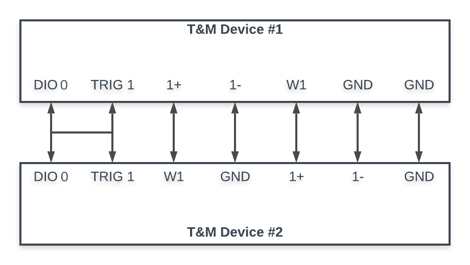
Make the following connections between the two devices' pins:
- Connect each device's analog input channel one positive pin (1+, orange cable) to the other device's waveform generator channel one pin (W1, yellow cable).
- Connect each device's analog input channel one negative pin (1-, orange and white cable) to a ground pin on either device (down arrow, black)
- Connect a ground pin from each device to a ground pin from the other device (down arrow, black).
- Connect each device's external trigger 1 pin (T1 or TRIG 1, grey cable) and digital output channel 0 pin (0 or DIO 0, pink cable) together, so that all four pins are connected to each other.
See the block diagram to the right for a visual representation of these connections.
Note: The connections are symmetrical, so it does not matter which device is considered “#1” and which is considered “#2”.
4.2.2 Software Setup
1. Open two instances of WaveForms.
2. Use each WaveForms instance's device manager to connect one device to each instance.
Note: In order to show each of the opened instruments on the screen at once, click on the Docking Windows button () at the top right corner of the window. To return to the default tabbed view later, click on the Tabbed Windows button () adjacent to the Docking Windows button.
3. In one WaveForms instance, henceforth referred to as the “primary instance”, open the following instruments, and configure them as described:
- Open a new Scope instrument and apply the following changes to its configuration:
- Set the Time Base to 500 us/div
- Set the Trigger Mode to Repeated and Normal
- Set the Trigger Source to Trigger 1
- Set the Trigger Condition Rising
- Disable the unused channels by unchecking their box
- Open a new Wavegen instrument and apply the following changes to its configuration:
- Set the Channel Synchronization to Independent
- Set Channel 1's Trigger Source to Trigger 1
- Set Channel 1's Wait Time to none
- Set Channel 1's Run Time to 2ms
- Set Channel 1's Simple Wave Frequency to 1kHz
- Set Channel 1's Simple Wave Type to Sine
- Open a new StaticIO instrument and apply the following changes to its configuration:
- Configure DIO 0 to be a button that outputs “0” when released and “1” when pressed.
- Open a new Script instrument.

4. In the other WaveForms instance, henceforth referred to as the “secondary instance”, open the following instruments, and configure them as described:
- Open a new Scope instrument and apply the following changes to its configuration:
- Set the Time Base to 500 us/div
- Set the Trigger Mode to Repeated and Normal
- Set the Trigger Source to Trigger 1
- Set the Trigger Condition to Rising
- Disable the unused channels by unchecking their box
- Open a new Wavegen instrument and apply the following changes to its configuration:
- Set the Channel Synchronization to Independent
- Set Channel 1's Trigger to Trigger 1
- Set Channel 1 Wait Time to none
- Set Channel 1 Run Time to 2 ms
- Set Channel 1 Simple Wave Frequency to 1 kHz
- Set Channel 1 Simple Wave Type to Square
- Open a new Script instrument.

5. Copy the code to the right into the primary instance's Script instrument.
{
  // Create a reference channel to contain the imported acquisition
  var r = Scope.Ref1.Range.value
  var o = Scope.Ref1.Offset.value
  Scope.Ref1.Clone(Scope.Channel1)
  Scope.Ref1.Range.value = r
  Scope.Ref1.Offset.value = o
  // Open the file exported by the secondary instance
  var f = File("1.bin")
  // Wait for the other instance to finish saving data
  for(var i = 0; i < 1000 && !f.exist(); i++);
  // Read data from the file and save it into the reference channel
  var rg = f.readDouble()
  f.deleteFile()
  Scope.Ref1.data = rg
}
6. Copy the code to the right into the secondary instance's Script instrument.
{
  // Create a binary file and write the channel 1 acquisition into it
  var f = File("1.bin")
  f.writeDouble(Scope.Channel1.alldata)
}
4.2.3 Operating the Multi-Device Cross Trigger Example
Now that the workspaces and hardware are set up, experimentation with the resulting system can begin.
This multi-device system connects the Wavegen and Scope instruments of the two devices together, so that all are triggered by the same external trigger, sourced from the primary device's digital input/output channel 0, which is driven by the StaticIO button.
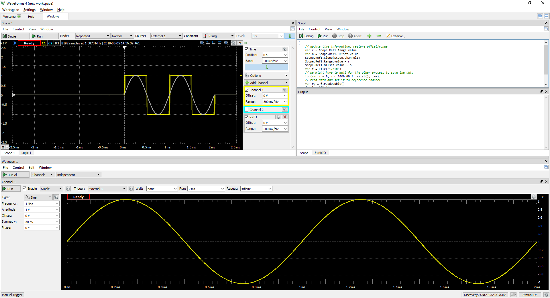
To capture data, first, click the Run button in each Scope and Wavegen instrument. Then, click the primary instance's StaticIO DIO 0 button to trigger all four instruments. Each device will play its wave for two milliseconds, which will then be captured by the other device's Scope. The results will look like the images to the right.


To view data captured by each device in the same plot, click the Run button in the secondary instance's Script instrument to export its captured data to a file. Then, click the Run button in the primary instance's Script instrument to import that data into its Scope as a Reference Channel. The result will look like the image to the right.
Using multi-device systems like this allows a user to greatly extend the number of analog signals that can be captured at once. For the Analog Discovery 2, each additional device adds another two analog input and output channels to the overall system, and digital I/O could easily be added as well. While the two captures are not perfectly aligned (each device runs on its own oscillator), the overall system may be good enough for use in some applications.
The WaveForms application was not designed to support more than one device at a time. However, WaveForms SDK is available for users that want to develop their own applications, and can readily support a large number of devices.
Next Steps
Especially when using multiple devices, the calibration (or lack thereof) of the devices may affect the ability to compare acquired data. For more information on calibrating your Test and Measurement device, see the Calibrating a Digilent Test and Measurement Device guide.
For more guides on how to use the Digilent Test and Measurement Device, return to the device's Resource Center, linked from the Test and Measurement page of this wiki.
For more information on WaveForms, visit the WaveForms Reference Manual.
For technical support, please visit the Test and Measurement section of the Digilent Forums.