Table of Contents
Decoding VGA Signals With a Portable Logic Analyzer
Logic Analyzers are useful tools for viewing, understanding, and decoding digital logic signals. Many allow you to decode common communication protocols, and even communicate with these protocols via a protocol analyzer.
Logic analyzers also come in a variety of sizes, prices, and speeds. With the release of the Digital Discovery from Digilent, you can now get a logic analyzer with sample rates up to 800MS/s for around $250.
This opens up the use of logic analyzers to many more applications. WaveForms is the free software that runs the device. With it you can do all the normal functionality of a logic analyzer, and write scripts to decode interfaces that are not automatically included.
In this tutorial, we'll use the Digital Discovery + High Speed Adapter to decode a VGA signal into an image. This can be useful when working on a VGA project, to see what signals are being sent correctly or incorrectly, and how they affect the final image. In the logic analyzer window you'll be able to see the VGA signals, and the script will save the resulting image.
Step 1: What You'll Need
- Logic Analyzer with Scripting
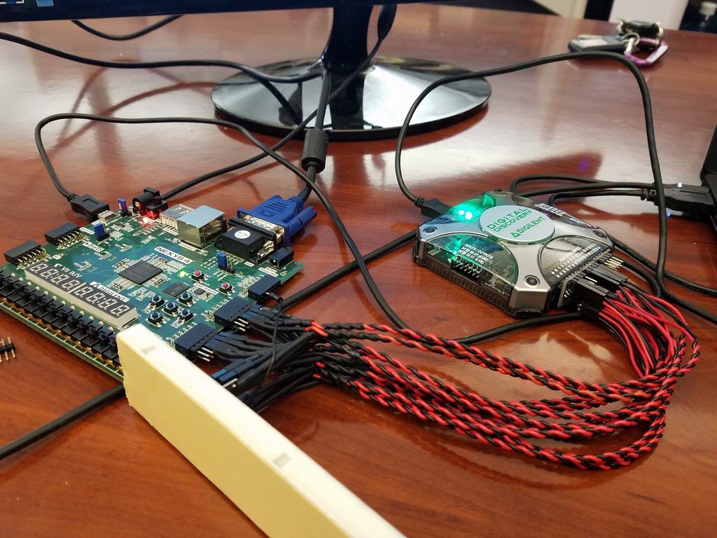
- In order to complete this project, you'll need a portable logic analyzer with sample rates up to 400MS/s and scripting capabilities. We chose the Digital Discovery with the High Speed Adapter. When used in combination, they can reach sample rates up to 800MS/s, which is more than enough. The Digital Discovery also has a scripting interface that gives access to write scripts using the logic analyzer. Below are all the individual components:
- Associated software
- The Digital Discovery comes with WaveForms, which is free to download. It also allowed us to save the configuration as a WaveForms project, so all you have to do is download that and open it. Everything will be configured and the script will be loaded.
- VGA Project
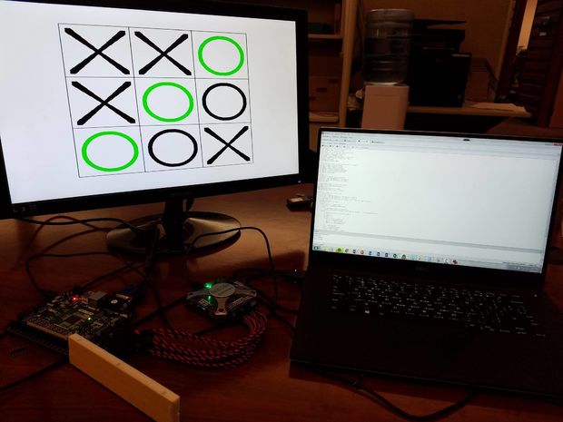
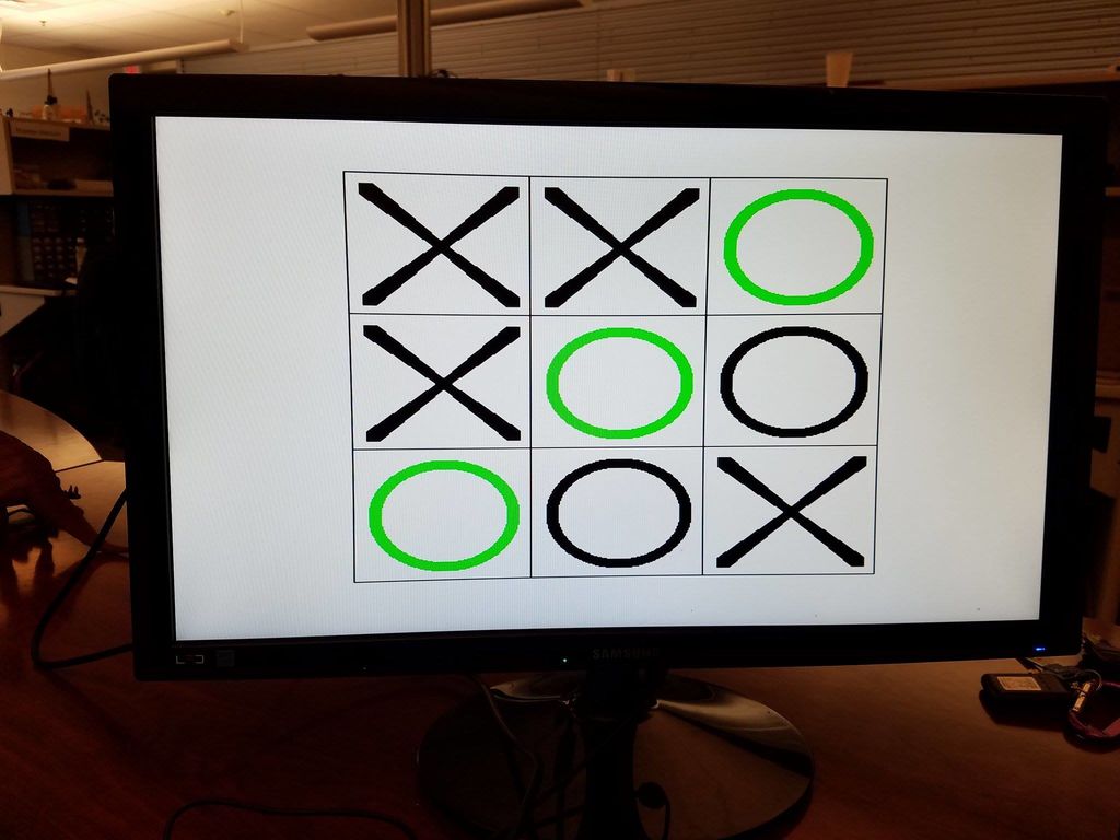
- You'll also need a VGA project where the VGA signals included HS, VS, and the 4 bits of all RGB signals are outputted to external pins. The script is currently written for 25MHz pixel frequency, and 480×640 resolution. We used a game of tic tac toe written by GitHub user artvvb, and modified it to output the VGA signals to the Pmod ports on the Nexys 4.
- An image viewer that can open ppm file types.
- The script outputs a ppm file, so you'll need something that can open that. We used Ifranview.
You can see the setup with all of the components in the figure below.
Step 2: Download the WaveForms Workspace
VGA Demo download
Once you get your VGA project up and running, the first thing you'll need to do is download the WaveForms workspace. This has the logic analyzer open with the correct acquisition settings for a standard VGA spec, the power supply interface set to interprate 3.3V as logic high, and the script editor open with the correct script.
Once it's downloaded, double-click to open it.
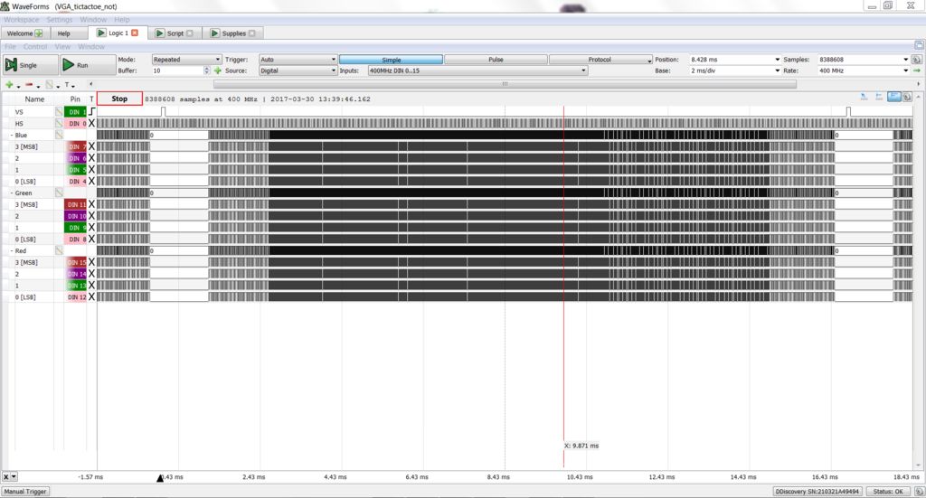
Then you'll want to run the logic analyzer to capture your data. It will automatically load with my data. Make sure that the window captures on window of data, i.e. the data between to vertical sync windows.
Note: If you don't have the Digital Discovery, you can download WaveForms and open this interface in DDiscovery Demo mode.
Step 3: Plug the High Speed Adapter Into the Digital Discovery

Next you'll need to setup the hardware.
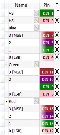
Plug the High Speed Adapter into the Digital Discovery, and connect 14 High Speed Logic Probes to DIO 0,1, and 4-15.
Step 4: Ground the High Speed Logic Probes

The High Speed Logic Probes reduce noise by grounding each signal, and including a terminating resistor.
Using the breadboard, plug all of the black ends of the High Speed Logic Probes into the same node, and connect that same node to your project's ground. In this case, we connected this node to the ground pin on one of the Pmod ports.
Step 5: Connect the High Speed Logic Probes to the VGA Signals
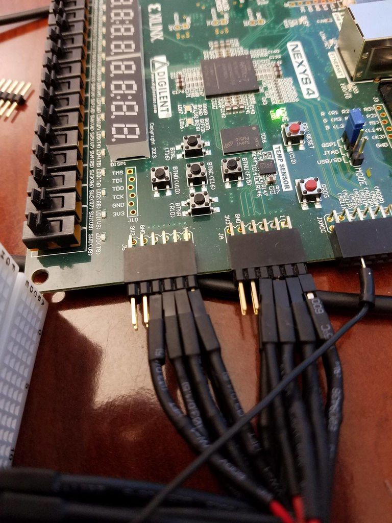
Connect the red side of the High Speed Logic Probes to the VGA signals of your project. For our configuration, that means connecting them to the pins on the Pmod ports that we had sent the VGA signals to.
You can see which DIO pins correspond to which VGA pins in the image of the logic analyzer signals above.
Step 6: Double-check that Everything is Connected Correctly
It is highly recommended that you take the time to make sure that everything is connected properly. You may regret it later on if you skip this step!
If you are using the same setup here and you see noise in the horizontal sync or vertical sync signals, something isn't grounded properly, or you have a faulty breadboard wire.
Step 7: Run the Script
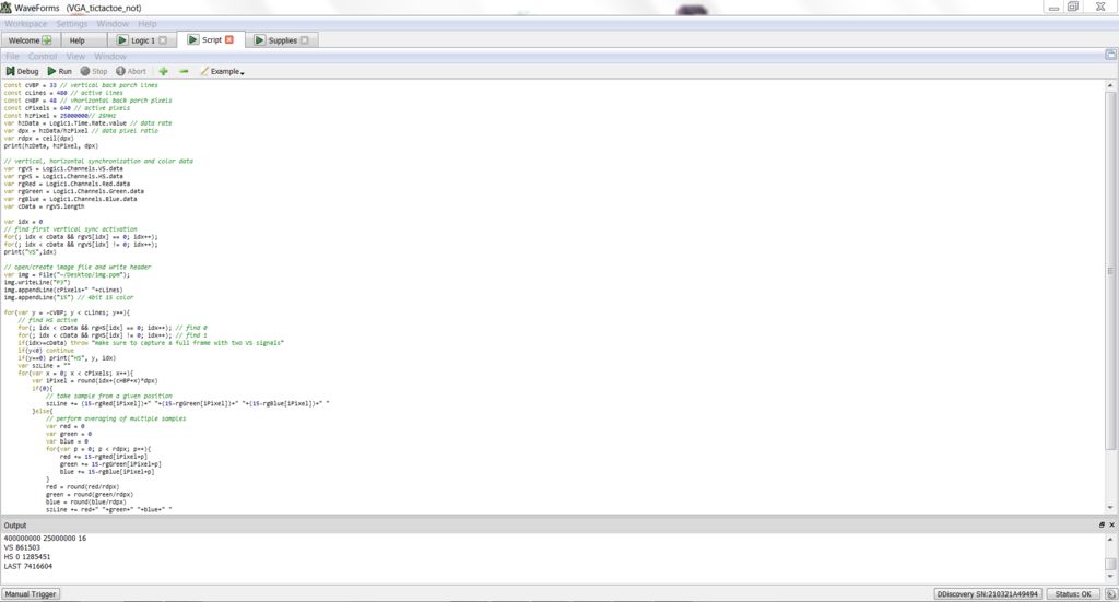
Next, go to the scripting interface and run the script. The video above displays the script running. It will take a few moments to run, and will be done when the stop button turns back into the run button.
Step 8: Open the Resulting Image
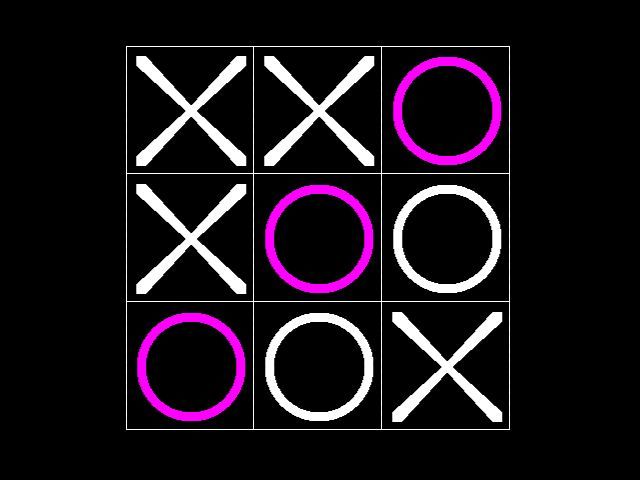
Next, you can open the resulting image. The script saves the image to the desktop as img.ppm. We converted this image to a type that can be easily viewed.
You can see that the image that is saved is actually a negative of the original image. This can be fixed if desired.