Table of Contents
Pmod PMON1 Reference Manual
The Digilent Pmod (Revision B) employs the Analog Devices AD5112 and ADM1191 to create a system power monitor.


Download This Reference Manual
Features
- Monitor current draw less than 1.058 A
- Wide range of configurable alert conditions
- Monitor voltages from 3.16 V to 26 V
- Configurable device address for up to nine modules in a single system
- 2×4-pin connector with I2C interface
Functional Description
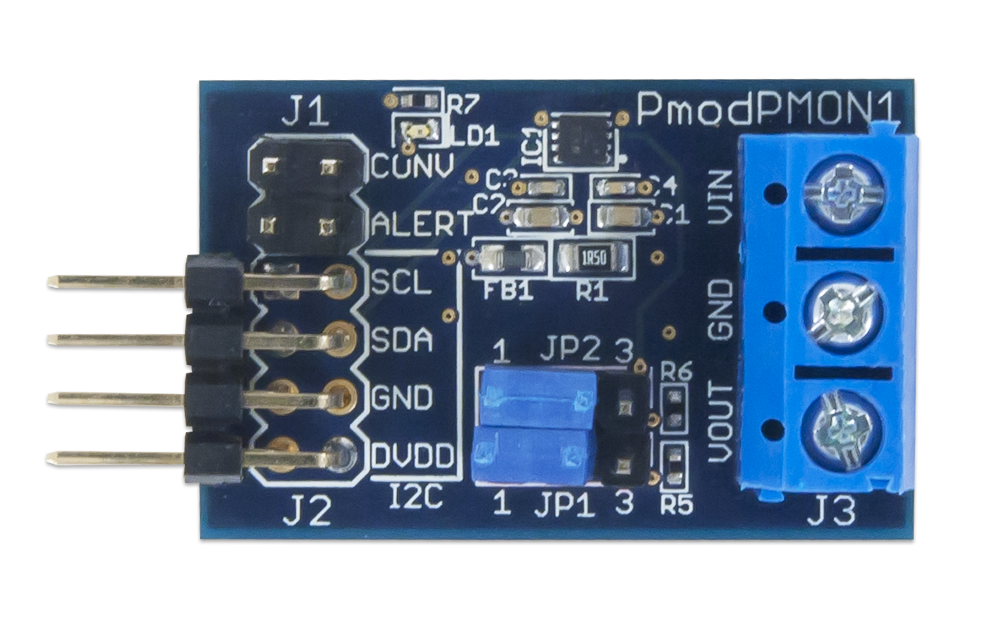
Users can configure the Pmod PMON1 to a wide range of possible alert conditions from the ADM1191 by using the configurable AD5112 potentiometer. The AD5112 upper potentiometer connection ties to DVDD through a filtering ferrite bead and the lower connection connects to GND. (See Table 1 for Connector Descriptions.) The wiper directly connects to the SETV pin on the ADM1191 to allow for the wide range of alert conditions. If an alert condition occurs, LD1 on the PMON1 will illuminate and the alert pin will go to a logic low state.
Interfacing with the Pmod
In order to use multiple Pmod PMON1s on a single I2C bus, each individual PMON1 will need to be connected; and the desired potentiometer value programmed into the EEPROM on the AD5112. Any stored value will become the default starting value for the potentiometer. The alert functionality available on the ADM1191 will not function properly without programming each individual device. (See Table 2 for jumper descriptions.)
Pinout Description Table
| Connector J1 - Control Pins | ||
|---|---|---|
| Pin | Signal | Description |
| 1 & 2 | CONV | Trigger a conversion |
| 3 & 4 | ALERT | Overcurrent or undervoltage event |
| Connector J2 - I2C Interface | ||
| Pin | Signal | Description |
| 1 & 2 | SCL | Serial clock |
| 3 & 4 | SDA | Serial data |
| 5 & 6 | GND | Ground |
| 7 & 8 | DVDD | Input voltage |
| Connector J3 - Power Monitor Screw Terminal | ||
| Pin | Signal | Description |
| 1 | VIN | Input voltage of device to monitor |
| 2 | GND | Ground |
| 3 | VOUT | Voltage supplies to device being monitored |
Pinout Description Table
| Jumper | Setting | Description |
|---|---|---|
| JP1 | 1 | ADM1191 Address bit 3 and 2 set to 0b00 |
| 3 | ADM1191 Address bit 3 and 2 set to 0b01 | |
| OFF | ADM1191 Address bit 3 and 2 set to 0b10 | |
| JP2 | 1 | ADM1191 Address bit 1 and 0 set to 0b00 |
| 3 | ADM1191 Address bit 1 and 0 set to 0b01 | |
| OFF | ADM1191 Address bit 1 and 0 set to 0b10 |
Any external power applied to the Pmod must be within 2.5V and 5.5V; however, it is recommended that Pmod is operated at 3.3V.
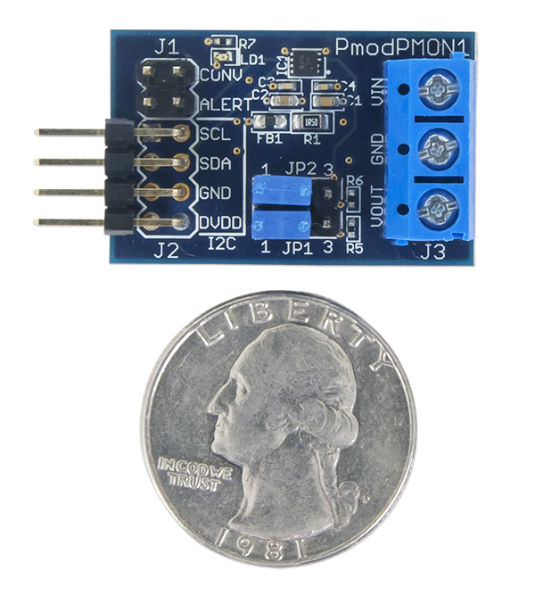
Physical Dimensions
The pins on the pin header are spaced 100 mil apart. The PCB is 1.2 inches long on the sides parallel to the pins on the pin header and 0.8 inches long on the sides perpendicular to the pin header.
Additional Information
The schematics of the Pmod PMON1 are available here. Additional information about the AD5112 and ADM1191 including communication modes and specific timings of the chip can be found by checking out its datasheet.
Example code demonstrating how to get information from the Pmod PMON1 can be found here.
If you have any questions or comments about the Pmod PMON1, feel free to post them under the appropriate section (“Add-on Boards”) of the Digilent Forum.