Table of Contents
Pmod OLEDrgb Reference Manual
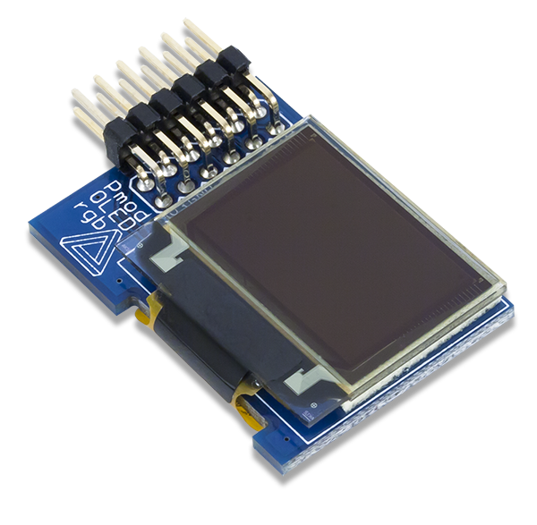
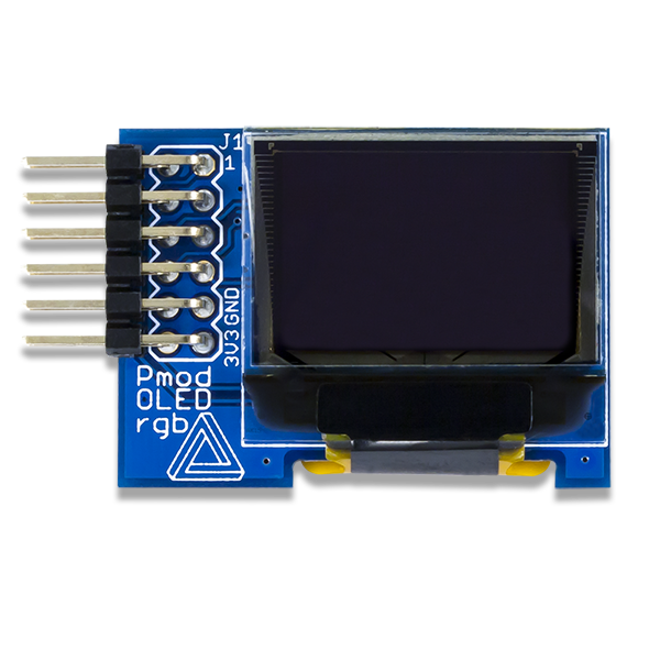
The Digilent Pmod OLEDrgb (Revision B) is an organic RGB LED module with a 96×64 pixel display capable of 16-bit color resolution.

Download This Reference Manual
Features
- 96×64 pixel RGB OLED screen
- 0.8“ x 0.5” graphical display
- 16-bit color resolution
- Two low-power display shutdown modes
- 12-pin Pmod connector with SPI interface
Functional Description
The Pmod OLEDrgb utilizes a Solomon Systech SSD1331 display controller to receive information from the host board and display the desired information on the OLED screen.
Specifications
| Parameter | Min | Typical | Max | Units |
|---|---|---|---|---|
| Power Supply Voltage | 2.7 | 3.3 | 3.5 | V |
| Parameter | Value | Units | ||
| Dark Room Contrast | >1000:1 | |||
| View Angle | >160 | degrees | ||
| Number of Pixels | 96 x 64 | |||
| Panel Size | 25.70 x 22.20 x 1.50 | mm | ||
| Active Area | 20.14 x 13.42 | mm | ||
| Pixel Pitch | 0.07 x 0.21 | mm | ||
| Pixel Size | 0.05 x 0.19 | mm | ||
| White Screen Current Consumption¹ | 75.5 | mA | ||
Note¹ - All pixels set to white at maximum brightness
Interfacing with the Pmod
The Pmod OLEDrgb communicates with the host board via the SPI protocol. By driving and keeping the Chip Select (CS) line at a logic level low, users may send both commands and data streams to the display controller based on the state of the Data/Command (D/C) pin. The display controller operates in SPI Mode 3 (clock idles on logic high, data is captured on the clock rising edge, and data is transferred on the clock falling edge) and with a minimum clock cycle time of 150 ns (as per table 21 of the SSD1331 datasheet). The embedded display only supports SPI write, so users will not be able to receive any information back from the display over SPI.
As a graphical display interface, users may light up any individual pixel on the OLED, display predefined characters, or even load bitmaps onto the screen. Each pixel can be set to one of the 65,535 colors that are available in a 5-6-5 bit RGB format. The OLED display has a specific power-up and power-down sequence to ensure the longevity of the device.
There are two field-effect transistors (FETs) that control the display’s two power supplies. The VCCEN control (pin 9) toggles the positive voltage supply to the screen itself and the PMODEN control (pin 10) toggles the power supply ground to the display. Users may turn off either one of these controls to reduce the power consumption of the Pmod OLEDrgb to approximately 200 nA.
Quick Data Acquisition
Power-on Sequence where the bytes provided are in the format of (command, data)
- Bring Data/Command control (pin 7) logic low.
- Bring the Reset pin (pin 8) logic high.
- Bring the Vcc Enable (pin 9) logic low.
- Bring Pmod Enable (pin 10) to logic high and delay 20 ms to allow the 3.3V rail to become stable.
- Bring RES (pin 8) logic low, wait for at least 3 us, and then bring it back to logic high to reset the display controller.
- Wait for the reset operation to complete; this takes a maximum of 3 us to complete.
- Enable the driver IC to accept commands by sending the unlock command over SPI (0xFD, 0x12).
SpiWriteMultiple(2, 0xFD, 0x12); //Write two bytes-- the (un)lock commands register and the byte value to set the register to unlock command mode
- Send the display off command.
SpiWrite(0xAE); //Turn off the display with a one byte command
- Set the Remap and Display formats (0xA0, 0x72), see page 29 of the datasheet for the 7 options that are affected by this command.
SpiWriteMultiple(2, 0xA0, 0x72); //Write two bytes-- the driver remap and color depth command and the single byte value
- Set the Display start Line to the top line (0xA1, 0x00).
SpiWriteMultiple(2, 0xA1, 0x00); //Write two bytes-- the set display start line command and the single byte value for the top line
- Set the Display Offset to no vertical offset (0xA2, 0x00).
SpiWriteMultiple(2, 0xA2, 0x00); //Write two bytes-- the command and the single byte value for no vertical offset)
- Make it a normal display with no color inversion or forcing the pixels on/off (0xA4).
SpiWrite(0xA4); //A single byte value for a normal display
- Set the Multiplex Ratio to enable all of the common pins calculated by 1+register value (0xA8, 0x3F). See page 30 of the datasheet for more details
SpiWriteMultiple(2, 0xA8, 0x3F); //Write two bytes-- the multiplex ratio command and the single byte value
- Set Master Configuration to use a required external Vcc supply (0xAD, 0x8E).
SpiWriteMultiple(2, 0xAD, 0x8E); //Write two bytes-- the master configuration command and the required single byte value of 0x8E
- Disable Power Saving Mode (0xB0, 0x0B).
SpiWriteMultiple(2, 0xB0, 0x0B); //Write two bytes-- the power saving mode command and the single byte value
- Set the Phase Length of the charge and discharge rates of an OLED pixel in units of the display clock See page 26 of the datasheet for more details.
SpiWriteMultiple(2, 0xB1, 0x31); //Write two bytes-- the set phase length command and the single byte value
- Set the Display Clock Divide Ratio and Oscillator Frequency, setting the clock divider ratio to 1 and the internal oscillator frequency to ~890 kHz. See Figure 28 on page 46 of the datasheet for more details.
SpiWriteMultiple(2, 0xB3, 0xF0); //Write two bytes-- the Clock ratio and oscillator frequency command and the single byte value
- Set the Second Pre-Charge Speed of Color A¹ to drive the color (red by default) to a target driving voltage. See page 26 and 37 of the datasheet for more details.
SpiWriteMultiple(2, 0x8A, 0x64); //Write two bytes-- the color A 2nd precharge speed command and the single byte value
- Set the Second Pre-Charge Speed of Color B¹ to drive the color (green by default) to a target driving voltage. See page 26 and 37 of the datasheet for more details.
SpiWriteMultiple(2, 0x8B, 0x78); //Write two bytes-- the color B 2nd precharge speed command and the single byte value
- Set the Second Pre-Charge Speed of Color C¹ to drive the color (blue by default) to a target driving voltage. See page 26 and 37 of the datasheet for more details.
SpiWriteMultiple(2, 0x8C, 0x64); //Write two bytes-- the color C 2nd precharge speed command and the single byte value
- Set the Pre-Charge Voltage to approximately 45% of Vcc to drive each color to a target driving voltage. See Figure 30 on page 47 of the datasheet for the definition of approximate. More details about the pre-charge voltage are available on pages 26 and 37.
SpiWriteMultiple(2, 0xBB, 0x3A); //Write two bytes-- the set precharge voltage command and the single byte value
- Set the VCOMH Deselect Level, which is the minimum voltage level to be registered as logic high, to 83% of Vcc.
SpiWriteMultiple(2, 0xBE, 0x3E); //Write two bytes-- the VCOMH Deselect level command and the single byte value
- Set Master Current Attenuation Factor to set a reference current for the segment drivers. See page 23 of the datasheet for the equation and more details.
SpiWriteMultiple(2, 0x87, 0x06); //Write two bytes-- the set master current attenuation factor command and the single byte value
- Set the Contrast for Color A (default red), effectively setting the brightness level. See the 4th bullet point on page 23 of the datasheet for the associated equation and more details.
SpiWriteMultiple(2, 0x81, 0x91); //Write two bytes-- the Color A contrast command and the single byte value
- Set the Contrast for Color B (default green), effectively setting the brightness level. See the 4th bullet point on page 23 of the datasheet for the associated equation and more details.
SpiWriteMultiple(2, 0x82, 0x50); //Write two bytes-- the Color B contrast command and the single byte value
- Set the Contrast for Color C (default blue), effectively setting the brightness level. See the 4th bullet point on page 23 of the datasheet for the associated equation and more details.
SpiWriteMultiple(2, 0x83, 0x7D); //Write two bytes-- the Color C contrast command and the single byte value
- Disable Scrolling.
SpiWrite(0x2E); //Write a single byte-- the disable scrolling command
- Clear the screen by sending the clear command and the dimensions of the window to clear (top column, top row, bottom column, bottom row).
SpiWriteMultiple(5, 0x25, 0x00, 0x00, 0x5F, 0x3F); //Write 5 bytes-- the clear command and the five bytes representing the area to clear
- Bring VCCEN (pin 9) logic high and wait 25 ms.
- Turn the display on.
SpiWrite(0xAF); //Write a single byte-- the turn display on command
- Wait at least 100 ms before further operation.
- Run one of the graphical commands either provided by Digilent or the display controller datasheet, explained in further detail after the Power-off sequence directly below this line.
Note¹ – when changing any of the second pre-charge speeds, all three registers must be updated sequentially with 6 bytes total (address A, value A, address B, value B, address C, value C), even if their values do not change.
Power-off Sequence
- Turn the display off.
SpiWrite(0xAE); //Write a single byte-- the turn display off command
- Bring Vcc Enable (pin 9) logic low.
- Delay 400 ms.
- Disconnect the positive voltage supply to the Pmod OLEDrgb.
Graphics funtions The SSD1331 display controller comes with a number of predefined graphical commands for the user to take advantage of and Digilent provides a few additional graphics functions (such as the displaying of ASCII characters and setting the cursor location) for use. The commands and associated parameters for the predefined functions are nicely outlined on pages 28 through 33 of the datasheet with further description of the functions available starting on page 35. The Digilent made commands can be found under Example Projects in the Pmod OLEDrgb Resource Center.
Pinout Description Table
| Header J1 | ||||||
|---|---|---|---|---|---|---|
| Pin | Signal | Description | Pin | Signal | Description | |
| 1 | CS | Chip Select | 7 | D/C | Data/Command Control | |
| 2 | MOSI | Master-Out-Slave-In | 8 | RES | Power Reset | |
| 3 | NC | Not Connected | 9 | VCCEN | Vcc Enable | |
| 4 | SCK | Serial Clock | 10 | PMODEN | Vdd Logic Voltage Control | |
| 5 | GND | Power Supply Ground | 11 | GND | Power Supply Ground | |
| 6 | VCC | Power Supply (3.3V) | 12 | VCC | Power Supply (3.3V) | |
Although users are welcome to create their own interface code for the Pmod OLEDrgb if they so desire, pre-constructed libraries that provide functions for initializing the display and rendering simple text and graphics onto the screen exist. They are available on the Pmod OLEDrgb Resource Center and can be used as-is or as a starting point for a more sophisticated graphics library.
Any external power applied to the Pmod OLEDrgb must be within 2.7V and 3.5V; however, it is recommended that Pmod is operated at 3.3V.
Physical Dimensions
The pins on the pin header are spaced 100 mil apart. The PCB is 1.4 inches long on the sides parallel to the pins on the pin header and 1 inch long on the sides perpendicular to the pin header.
Additional Information
The schematics of the Pmod OLEDrgb are available here. Additional information about the display controller including communication modes and specific timings of the chip can be found by checking out its datasheet here. Similarly, the datasheet for the display can be found here.
Example code demonstrating how to get information from the Pmod OLEDrgb can be found here.
If you have any questions or comments about the Pmod OLEDrgb, feel free to post them under the appropriate section (“Add-on Boards”) of the Digilent Forum.