Table of Contents
Pmod HYGRO Reference Manual
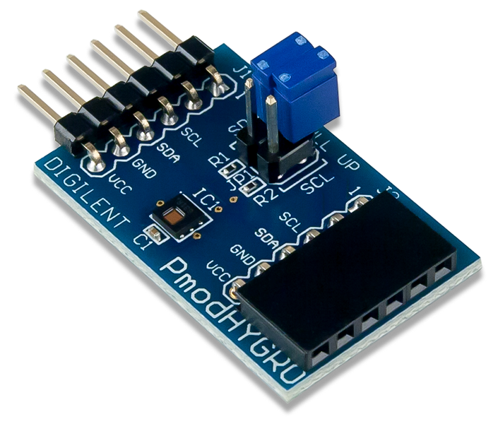
The Digilent Pmod HYGRO (Revision A) is a relative humidity sensor with an integrated temperature sensor for highly accurate measurements at low power. With the TI HDC1080, you can determine the relative humidity of the environment with up to 14 bits of resolution.


Download This Reference Manual
Features
- Relative humidity accuracy ±2%
- Temperature sensor accuracy 0.2 °C
- Good stability at high humidity
- 14-bit measurement resolution
- Internal resistive heating element
- 6-pin Pmod connector with I²C interface
- Pass-through Pmod host port for daisy chaining
Functional Description
The Pmod HYGRO is designed to digitally report the relative humidity and ambient temperature upon request by the host board. Up to 14-bits of resolution for each sensor may be collected by allowing for longer conversion times. A resistive heating element can be enabled to test the sensor or drive off condensation that accumulates on the sensor after being consistently exposed to high humidity conditions.
Specifications
| Parameter | Min | Typical | Max | Units |
|---|---|---|---|---|
| Power Supply Voltage | 2.7 | 3 | 5.5 | V |
| Serial Clock Frequency | 10 | 400 | kHz | |
| Parameter | Value | Units | ||
| RH Accuracy | ±2 | %RH | ||
| RH Repeatability | ±0.1 | %RH | ||
| RH Hysteresis | ±1 | %RH | ||
| RH Response Time | 15 | sec | ||
| Temperature Accuracy | ±0.2 | °C | ||
| Sleep Mode Current Draw | 100 | nA | ||
Interfacing with the Pmod
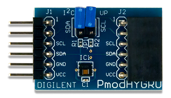
The Pmod HYGRO communicates with the host board via the I²C protocol. By first sending the 7-bit I²C address of 1000000 (0x40) and then a read/write bit (high/low logic level, respectively), followed by the register address of interest at a maximum clock frequency of 400 kHz, users can both configure and read from the Pmod HYGRO. Header J2 on the Pmod HYGRO passes through all of the signals present on the main Header J1 to allow for the daisy chaining of multiple I²C compatible modules.
Configuration Register
The Configuration register (address 0x02) allows users to control the resolution of the temperature and humidity measurements, change the acquisition mode, enable the heater, and more. A table of the 16-bit register, recreated from Table 4 in the HDC1080 datasheet, is provided below.
| Configuration Register Description (Address 0x02) | ||||
|---|---|---|---|---|
| Bit Name | Bit Number | Bit Description | Bit Values | Functional Description |
| RST | [15] | Software reset bit | 0¹ | Normal Operation, this bit self clears |
| 1 | Software Reset | |||
| Reserved | [14] | Reserved | 0 | Reserved, must be 0 |
| HEAT | [13] | Heater | 0¹ | Heater Disabled |
| 1 | Heater Enabled | |||
| MODE | [12] | Acquisition Mode | 0 | Temperature or Humidity is acquired depending on which register you choose to read |
| 1¹ | Temperature and Humidity are acquired in sequence, with the Temperature first | |||
| BTST | [11] | Battery Status | 0¹ | Battery voltage (Vdd) > 2.8V (read only) |
| 1 | Battery voltage (Vdd) < 2.8V (read only) | |||
| TRES | [10] | Temperature Measurement Resolution | 0¹ | 14 bit |
| 1 | 11 bit | |||
| HRES | [9:8] | Humidity Measurement Resolution | 00¹ | 14 bit |
| 01 | 11 bit | |||
| 10 | 8 bit | |||
| Reserved | [7:0] | Reserved | 0 | Reserved, must be 0 |
¹ – This is the default value on power-up or reset
Temperature and Humidity Registers
The temperature register (address 0x00) and the humidity register (address 0x01) are both 16-bit read only registers with the 14 MSBs corresponding to the 14-bit maximum resolution for both sensors. The two LSBs (bits D1 and D0) are always 0 for both registers. As the measurement resolution increases, the corresponding conversion time for each sensor also increases. A table of typical conversion times from Section 7.5 (Electrical Characteristics) of the HDC1080 datasheet, is provided below.
| Relative Humidity Sensor | Temperature Sensor | ||
|---|---|---|---|
| 8-bit resolution | 2.50 ms | 11-bit resolution | 3.65 ms |
| 11-bit resolution | 3.85 ms | 14-bit resolution | 6.35 ms |
| 14-bit resolution | 6.50 ms | ||
Upon device power-up, the Pmod HYGRO requires at least 15 ms prior to being able to perform a measurement. To perform a measurement, users need to configure (or accept) the measurement settings in the Configuration Register, and then trigger the measurement(s) by sending an I²C write transaction along with the address pointer set to the appropriate register. After waiting the appropriate conversion times, users may then perform a read transaction, taking advantage of the auto-incrementing pointer address for reading both the temperature and humidity registers. After the data has been read, users need to wait at least one full second before performing another read transaction to avoid internal heating of the sensor and the distortion of the measured temperature and humidity levels.
Note that if a write transaction is performed on either the temperature (address 0x00) or humidity (address 0x01) registers during a conversion, the current conversion will be aborted and a new one started. If a read is performed during a conversion, the Pmod HYGRO will respond back with a NACK indicating the measurement result is not yet available. The typical time that it takes the output of the humidity sensor to show 63% of a step change in humidity is 15 seconds.
Quick data acquisition
Here is the series of commands to acquire relative humidity and temperature data from the Pmod HYGRO in pseudo I²C code.
- Power on the Pmod HYGRO and wait at least 15 ms.
- Call the device ID with a write bit
I2CBegin(0x80); //device ID 0x40 with a write (0) bit
- Wait to receive an ACK from the Slave Device
- Write the device address that you want to talk to
I2CWrite(0x00); //address 0x00 corresponds to the Temperature Register, the Humidity register will be auto-incremented to next
- Wait to receive an ACK from the Slave Device
- Delay at least 12.85 ms (6.35 ms for the Temperature Sensor and 6.50 ms for the Humidity Sensor)
- Read 4 bytes from the temperature and humidity registers (two 8 byte samples from each, MSB then LSB)
I2CReadMultiple(4); //read four bytes, sending an ACK to the slave after each byte received and a NACK after the last byte
- Convert the readings into usable data. Note that the two LSBs (D1 and D0) will always be set to a value of
0. Only the upper 14-bits in each register contains the relevant data.
$Temperature(°C) = \dfrac{Temperature\ [15:00]}{2^{16}} * 165°C - 40°C$
$Relative\ Humidity\ (\% RH) = \dfrac{Humidity\ Register[15:0]}{2^{16}} * 100\%RH$ - Wait at least one full second before initiating another reading to avoid internal heating of the humidity sensor.
Pinout Table Diagram
| Header J1 | Header J2 | Jumper Blocks | ||||||
|---|---|---|---|---|---|---|---|---|
| Pin | Signal | Description | Pin | Signal | Description | Jumper | State | Description |
| 1 | NC | Not Connected | 1 | NC | Not Connected | JP1 | Both Enabled | 2.2 kΩ resistors enabled on the SDA and SCL lines |
| 2 | NC | Not Connected | 2 | NC | Not Connected | JP1 | Both Disabled | 2.2 kΩ resistors disabled on the SDA and SCL lines |
| 3 | SCL | Serial Clock | 3 | SCL | Serial Clock | |||
| 4 | SDA | Serial Data | 4 | SDA | Serial Data | |||
| 5 | GND | Power Supply Ground | 5 | GND | Power Supply Ground | |||
| 6 | VCC | Power Supply (3.3V/5V) | 6 | VCC | Power Supply (3.3V/5V) | |||
The Pmod HYGRO is an ideal Pmod to use in long term humidity test application. As a very low power Pmod between measurements, long term data to measure humidity changes in an environment can easily be collected.
Any external power applied to the Pmod HYGRO must be within 2.7 V and 5.5 V to ensure that the on-board chips operate correctly; however, it is recommended that Pmod is operated at 3.3 V.
Timing Diagram
A sample timing diagram for writing to and reading from the Pmod HYGRO taken from the HDC1080 datasheet are provided below:
Example write to the Pmod HYGRO

Example reading from the Pmod HYGRO

Physical Dimensions
The pins on the pin header are spaced 100 mil apart. The PCB is 1.25 inches long on the sides parallel to the pins on the pin header and 0.8 inches long on the sides perpendicular to the pin header.
Additional Information
The schematics of the Pmod HYGRO are available here. Additional information about the humidity sensor including communication modes and specific timings of the chip can be found by checking out its datasheet here.
More specific information about how to use the Pmod HYGRO can be found by checking out the additional resources on the Pmod HYGRO Resource Center. Example code demonstrating how to get information from the Pmod HYGRO can be found on its Resource Center here.
If you have any questions or comments about the Pmod HYGRO, feel free to post them under the appropriate section (“Add-on Boards”) of the Digilent Forum.