Adapting Projects Using the Zmod Scope for the Zmod Digitizer
Introduction
Digilent does not currently provide any example projects on Github for the Zmod Digitizer 1430-105. That said, there are several different projects for the Zmod Scope that can be adapted. The controller IPs for the two Zmods have highly similar hardware interfaces and can be swapped out without much difficulty. This guide walks through the process of doing so for one of these demos.
Required Materials
- An Eclypse Z7, Zmod Digitizer, and Zmod AWG
- The Vivado project for the Eclypse Z7 Low Pass Filter Demo
- This guide assumes the use of Vivado 2021.1 with an upgraded project. Other versions will likely work as-is, however, they haven't been tested.
- A version of Digilent's vivado-library that includes the ZmodDigitizerController: vivado-library-zmod-digitizer-1.0.zip
Guide
The following instructions assume you have a version of the Eclypse Z7's Low Pass Filter demo opened. The process of switching out the controllers in other projects and other versions is very similar. It should be noted that no AXI adapter is provided as of the time of writing, so many of the automatically configurable options will be manually set in the IP configuration.
These changes are specific to this demo, however, they are intended to show the thought process. We'll be making changes so that the Digitizer's onboard clock generator will be used as the clock source for the filter pipeline, in addition to changing the sample rate to 50 MS/s.
1.
First, you need a version of vivado-library that includes the Zmod Digitizer Controller in the project. Download it, then extract the downloaded ZIP archive. The zmod/digitizer/1.0 release can be downloaded here: vivado-library-zmod-digitizer-1.0.zip.
Navigate to your Vivado projects' IP repo settings and add the freshly downloaded repository to the list.
Note that some other IP may have changed which means that replacing the repo this way would require them to be upgraded. If you want to only add the Digitizer IP, you can always copy it out of the downloaded repo into the IP repo that has already been added to the project.
OK and confirm your way back out of the project settings.
2.
Upgrade existing IP to their latest versions. Use the Tools → Report IP Status option to upgrade all IP to their latest versions.
3.
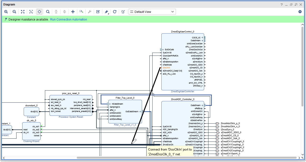
Add the Digitizer IP to the block design. Move it close to the Scope IP to make it easier to make connections between the two.
4.
Make the following connections between Digitizer inputs and Scope inputs. Change the top-level port names to match, so that they correspond to the port names used in an XDC that will be provided below.
| Digitizer IP Port | Scope IP Port | Top-Level Port Name |
|---|---|---|
| SysClk100 | SysClk100 | N/A |
| aRst_n | aRst_n | N/A |
| diZmodADC_Data | dZmodADCData | dZmodDigitizer_Data_0 |
| DcoClkIn | ZmodDcoClk | ZmodDcoClk_0 |
5.
Connect the following output ports to the Digitizer instead of the Scope. This can be accomplished by deleting the corresponding nets (not the ports) and making a new connection to the corresponding Digitizer Port. Change the top-level port names to match (to ensure they correspond to the port names used in an XDC that will be provided below).
| Digitizer IP Port | Scope IP Port | Top-Level Port Name |
|---|---|---|
| sZmodADC_SDIO | sZmodADC_SDIO | sZmodDigitizer_SDIO_0 |
| sZmodADC_CS | sZmodADC_CS | sZmodDigitizer_CS_0 |
| sZmodADC_Sclk | sZmodADC_Sclk | sZmodDigitizer_Sclk_0 |
| CG_InputClk_p | ZmodADCClkIn_p | ZmodCDCEClkIn_p_0 |
| CG_InputClk_n | ZmodADCClkIn_n | ZmodCDCEClkIn_n_0 |
6.
Make the following Digitizer output ports external, then rename the new ports as follows:
| Digitizer IP Port | Top-level port |
|---|---|
| CDCE_IIC | CDCE_IIC |
| aZmodSync | aZmodSync_0 |
| aREFSEL | REFSEL |
| aHW_SW_CTRL | HW_SW_CTRL |
| sPDNout_n | PDN |
7.
Delete the data stream interface net between the filter IP and the Scope controller IP, then make a new connection to the Digitizer.
8.
At this point, the Scope controller IP is no longer required. Delete it from the design. Clean up the rest of the now-disconnected ports.
Tie the EnableAcquisition port high. This port doesn't exist in earlier versions of the Scope IP and is intended to allow higher-level controllers to control when data begins streaming into the rest of the design. This demo is low-level and has no need to delay the enable.
Make sure the TestMode port is tied low. This will ensure that data is passed through the calibration module, rather than bypassing it.
Add a Utility Vector Logic 1-bit and gate to the design, make both of its inputs external, and rename them “GPIO1” and “GPIO4”. These signals indicate that the Zmod's on-board clock generator's PLL is locked. Connect its output to the Digitizer controller's aCG_PLL_Lock port.
Tie the filter IP's sInitDoneADC port to the corresponding port on the Digitizer controller.
Tie the filter IP's sInitDoneRelay port high - the Zmod Digitizer doesn't have any relays that need to be initialized before data starts flowing.
9.
Customize the Zmod Digitizer Controller IP. In particular, set the clock frequency to 50 MHz and disable external calibration coefficients. This demo will use default clock generator settings - using the Zmod Digitizer's onboard clock.
If you have the calibration coefficients for your particular Zmod Digitizer, you should enter them into the corresponding tab now, otherwise, leaving them as their defaults will cause the calibration module to pass unmodified data through to the AXI4-stream interface - multiplying by a fixed-point equivalent of 1.0 and adding 0. Not applying the calibration can significantly affect the performance of the filter. If you haven't pulled them, they are stored in nonvolatile memory in the Syzygy DNA. They can be extracted by using software sources available in the Digilent Platform Manager Utility repository with an appropriate baremetal software project - any project which uses the Zynq PS preset is sufficient since communication with DNA occurs via a PS MIO I2C controller.
Note that the 50 MHz clock frequency is coupled with several other settings in this particular demo - particularly the filter design. Your system might require other frequencies.
10.
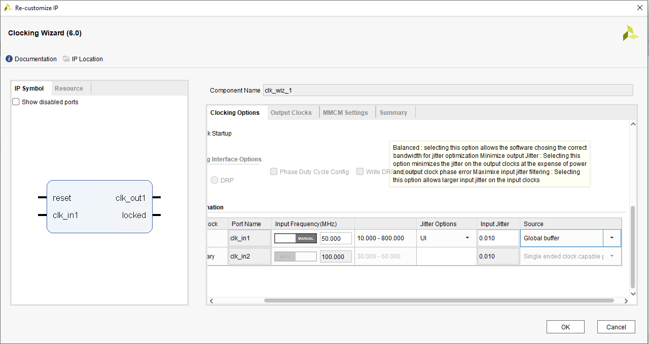
For the clocking wizard (clk_wiz_0) already included in the design, change clk_out1's frequency to 100 MHz, and disable the other two clocks. They are no longer needed.
11.
The demo's clocking architecture needs to be modified. Instead of the Eclypse system clock being used to generate all of the clocks, the Zmod's on-board clock will be used. Disconnect the filter's Sampling clock port and the AWG controller's DAC_InIO_Clk clock port. Connect each of them to the Digitizer controller's ZmodDcoClkOut port.
Tie the Digitizer controller's ClockGenPriRefClk input low. Because the Zmod's on-board clock is used here, it isn't required.
12.
Add a new clocking wizard to the design. It will be used to generate the 90-degree phase-shifted version of the Zmod's generated 50 MHz clock. Connect it to the Digitizer controller's ZmodDcoClkOut port and the AWG controller's DAC_Clk clock port. Make sure that clk_in1 is coming from a global buffer.
15.
Make sure to replace the existing constrs_1.xdc file contents with the constraints below, which will take care of constraining the renamed and newly-added ports.
- constr_1.xdc
-
set_property PACKAGE_PIN C17 [get_ports reset_rtl_0_0]
set_property IOSTANDARD LVCMOS33 [get_ports reset_rtl_0_0]
set_property PACKAGE_PIN D18 [get_ports clk_in1_0]
set_property IOSTANDARD LVCMOS33 [get_ports clk_in1_0]

#DAC

set_property PACKAGE_PIN Y19 [get_ports {dZmodDAC_Data_0[0]}]
set_property PACKAGE_PIN Y18 [get_ports {dZmodDAC_Data_0[1]}]
set_property PACKAGE_PIN AB22 [get_ports {dZmodDAC_Data_0[2]}]
set_property PACKAGE_PIN AB20 [get_ports {dZmodDAC_Data_0[3]}]
set_property PACKAGE_PIN AA18 [get_ports {dZmodDAC_Data_0[4]}]
set_property PACKAGE_PIN AA19 [get_ports {dZmodDAC_Data_0[5]}]
set_property PACKAGE_PIN Y21 [get_ports {dZmodDAC_Data_0[6]}]
set_property PACKAGE_PIN Y20 [get_ports {dZmodDAC_Data_0[7]}]
set_property PACKAGE_PIN V15 [get_ports {dZmodDAC_Data_0[8]}]
set_property PACKAGE_PIN V14 [get_ports {dZmodDAC_Data_0[9]}]
set_property PACKAGE_PIN AB15 [get_ports {dZmodDAC_Data_0[10]}]
set_property PACKAGE_PIN AB14 [get_ports {dZmodDAC_Data_0[11]}]
set_property PACKAGE_PIN W13 [get_ports {dZmodDAC_Data_0[12]}]
set_property PACKAGE_PIN V13 [get_ports {dZmodDAC_Data_0[13]}]

set_property IOSTANDARD LVCMOS18 [get_ports -filter { name =~ dZmodDAC_Data_0*}]

set_property PACKAGE_PIN W16 [get_ports ZmodDAC_Clkin_0]
set_property IOSTANDARD LVCMOS18 [get_ports ZmodDAC_Clkin_0]
set_property PACKAGE_PIN W17 [get_ports ZmodDAC_ClkIO_0]
set_property IOSTANDARD LVCMOS18 [get_ports ZmodDAC_ClkIO_0]

#DAC SPI
set_property PACKAGE_PIN Y14 [get_ports sZmodDAC_SDIO_0]
set_property IOSTANDARD LVCMOS18 [get_ports sZmodDAC_SDIO_0]
set_property DRIVE 4 [get_ports sZmodDAC_SDIO_0]
set_property PACKAGE_PIN AA14 [get_ports sZmodDAC_CS_0]
set_property IOSTANDARD LVCMOS18 [get_ports sZmodDAC_CS_0]
set_property DRIVE 4 [get_ports sZmodDAC_CS_0]
set_property PACKAGE_PIN AA13 [get_ports sZmodDAC_SCLK_0]
set_property IOSTANDARD LVCMOS18 [get_ports sZmodDAC_SCLK_0]
set_property DRIVE 4 [get_ports sZmodDAC_SCLK_0]

set_property PACKAGE_PIN W15 [get_ports sZmodDAC_SetFS1_0]
set_property IOSTANDARD LVCMOS18 [get_ports sZmodDAC_SetFS1_0]
set_property PACKAGE_PIN Y15 [get_ports sZmodDAC_SetFS2_0]
set_property IOSTANDARD LVCMOS18 [get_ports sZmodDAC_SetFS2_0]
set_property PACKAGE_PIN Y13 [get_ports sZmodDAC_Reset_0]
set_property IOSTANDARD LVCMOS18 [get_ports sZmodDAC_Reset_0]
set_property PACKAGE_PIN AA22 [get_ports sZmodDAC_EnOut_0]
set_property IOSTANDARD LVCMOS18 [get_ports sZmodDAC_EnOut_0]

#Zmod ADC

set_property PACKAGE_PIN T16 [get_ports GPIO1]
set_property IOSTANDARD LVCMOS18 [get_ports GPIO1]
set_property PACKAGE_PIN T17 [get_ports CDCE_IIC_scl_io]
set_property IOSTANDARD LVCMOS18 [get_ports CDCE_IIC_scl_io]
set_property PACKAGE_PIN R19 [get_ports CDCE_IIC_sda_io]
set_property IOSTANDARD LVCMOS18 [get_ports CDCE_IIC_sda_io]
set_property PACKAGE_PIN T19 [get_ports GPIO4]
set_property IOSTANDARD LVCMOS18 [get_ports GPIO4]
set_property PACKAGE_PIN N15 [get_ports HW_SW_CTRL]
set_property IOSTANDARD LVCMOS18 [get_ports HW_SW_CTRL]
#set_property PACKAGE_PIN P15 [get_ports SC1_GAIN_L_0]
#set_property IOSTANDARD LVCMOS18 [get_ports SC1_GAIN_L_0]
set_property PACKAGE_PIN P17 [get_ports PDN]
set_property IOSTANDARD LVCMOS18 [get_ports PDN]
set_property PACKAGE_PIN P18 [get_ports REFSEL]
set_property IOSTANDARD LVCMOS18 [get_ports REFSEL]
#set_property PACKAGE_PIN J20 [get_ports SC_COM_H_0]
#set_property IOSTANDARD LVCMOS18 [get_ports SC_COM_H_0]
#set_property PACKAGE_PIN K21 [get_ports SC_COM_L_0]
#set_property IOSTANDARD LVCMOS18 [get_ports SC_COM_L_0]
# ADC
set_property PACKAGE_PIN R18 [get_ports sZmodDigitizer_SDIO_0]
set_property IOSTANDARD LVCMOS18 [get_ports sZmodDigitizer_SDIO_0]
set_property DRIVE 4 [get_ports sZmodDigitizer_SDIO_0]
set_property PACKAGE_PIN M21 [get_ports sZmodDigitizer_CS_0]
set_property IOSTANDARD LVCMOS18 [get_ports sZmodDigitizer_CS_0]
set_property DRIVE 4 [get_ports sZmodDigitizer_CS_0]
set_property PACKAGE_PIN T18 [get_ports sZmodDigitizer_Sclk_0]
set_property IOSTANDARD LVCMOS18 [get_ports sZmodDigitizer_Sclk_0]
set_property DRIVE 4 [get_ports sZmodDigitizer_Sclk_0]
set_property PACKAGE_PIN M22 [get_ports aZmodSync_0]
set_property IOSTANDARD LVCMOS18 [get_ports aZmodSync_0]
set_property DRIVE 4 [get_ports aZmodSync_0]
set_property SLEW SLOW [get_ports aZmodSync_0]
set_property PACKAGE_PIN M19 [get_ports ZmodDcoClk_0]
set_property IOSTANDARD LVCMOS18 [get_ports ZmodDcoClk_0]

set_property IOSTANDARD DIFF_SSTL18_I [get_ports -filter { name =~ ZmodCDCEClkIn* }]
set_property PACKAGE_PIN N19 [get_ports ZmodCDCEClkIn_p_0]
set_property PACKAGE_PIN N20 [get_ports ZmodCDCEClkIn_n_0]
set_property SLEW SLOW [get_ports -filter { name =~ ZmodCDCEClkIn* }]

#14 bit
set_property PACKAGE_PIN N22 [get_ports {dZmodDigitizer_Data_0[0]}]
set_property PACKAGE_PIN L21 [get_ports {dZmodDigitizer_Data_0[1]}]
set_property PACKAGE_PIN R16 [get_ports {dZmodDigitizer_Data_0[2]}]
set_property PACKAGE_PIN J18 [get_ports {dZmodDigitizer_Data_0[3]}]
set_property PACKAGE_PIN K18 [get_ports {dZmodDigitizer_Data_0[4]}]
set_property PACKAGE_PIN L19 [get_ports {dZmodDigitizer_Data_0[5]}]
set_property PACKAGE_PIN L18 [get_ports {dZmodDigitizer_Data_0[6]}]
set_property PACKAGE_PIN L22 [get_ports {dZmodDigitizer_Data_0[7]}]
set_property PACKAGE_PIN K20 [get_ports {dZmodDigitizer_Data_0[8]}]
set_property PACKAGE_PIN P16 [get_ports {dZmodDigitizer_Data_0[9]}]
set_property PACKAGE_PIN K19 [get_ports {dZmodDigitizer_Data_0[10]}]
set_property PACKAGE_PIN J22 [get_ports {dZmodDigitizer_Data_0[11]}]
set_property PACKAGE_PIN J21 [get_ports {dZmodDigitizer_Data_0[12]}]
set_property PACKAGE_PIN P22 [get_ports {dZmodDigitizer_Data_0[13]}]
set_property IOSTANDARD LVCMOS18 [get_ports -filter { name =~ dZmodDigitizer_Data_0*}]
After validating your block diagram and generating a bitstream, you will have a bitstream you can use with the Zmod Digitizer! Note that you may also need to delete and recreate the block design's HDL wrapper to ensure that top-level port map changes are properly synced.
Next Steps
For more guides on how to use the Zmod Digitizer, return to its Resource Center: Zmod Digitizer.
For designing your own systems around the Zmod Digitizer and its controller, the Zmod Digitizer Controller User Guide is the single best place to find more information on its use. Note that you can also access this documentation from within Vivado by right-clicking on the controller and selecting IP Documentation → View Product guide.
For technical support, please visit the FPGA section of the Digilent Forums.


