Using the Static I/O
Introduction
This guide explains the use of the Static I/O instrument in WaveForms. This instrument is used to interact with a Test & Measurement Device's digital input/output channels through simulated buttons, LEDs, displays, and sliders.
Prerequisites
- A Digilent Test & Measurement Device with Digital Output Channels:
- A Computer with WaveForms Software Installed
Guide
1. Opening the Static I/O
1.1
Plug in the Test & Measurement Device, then start WaveForms and make sure the device is connected.
If no device is connected to the host computer when WaveForms launches, the Device Manager will be launched. Make sure that the device is plugged in and turned on, at which point it will appear in the Device Manager's device list (1). Click on the device in the list to select it, then click the Select button (2) to close the Device Manager.
Note: “Demo” devices are also listed, which allow the user to use WaveForms and create projects without a physical device.
Note: The Device Manager can be opened by clicking on the “Connected Device” button in the bottom right corner of the screen (3), or by selecting “Device Manager” from the “Settings” menu at the top of the screen.
1.2
Once the Welcome page loads, in the instrument panel at the left side of the window, click on the StaticIO button to open the Static I/O instrument.

1.3
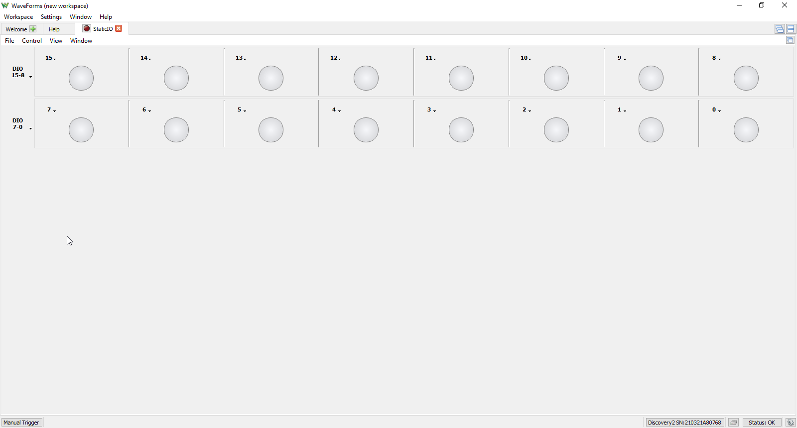
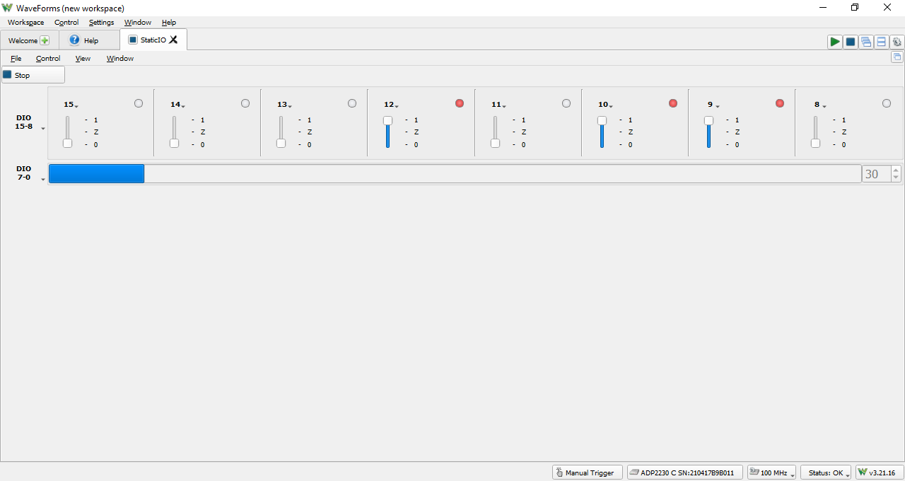
Once the Static I/O instrument opens, the window contains Bit I/O digital input and output ports for each of the device's digital I/Os, all assigned to LED state indicators by default. The instrument should be started with the green play button, or from the Menu Bar, under the Control menu point with the Run option.
2. Using the Static I/O
This section walks through setting up the StaticIO instrument to display and interact with digital I/O ports and their logic levels. The Logic Analyzer will be used to view the state of the output of a virtual button. The Pattern Generator will be used to blink a virtual LED.
Note: This guide can be followed using a “Demo” device selected in the WaveForms Device Manager. Doing so allows the user to follow along without having access to a real test and measurement device.
Important
When using the Static I/O with real hardware, note that the digital channels are not meant to be used as sources for large loads. Don't connect much more than a single LED and resistor directly to the channel. If larger loads need to be driven, the digital input/output channels can be used to trigger high current drivers such as MOSFETs, H-bridges, etc., but are not to be used as primary sources.
2.1 Software Display Setup
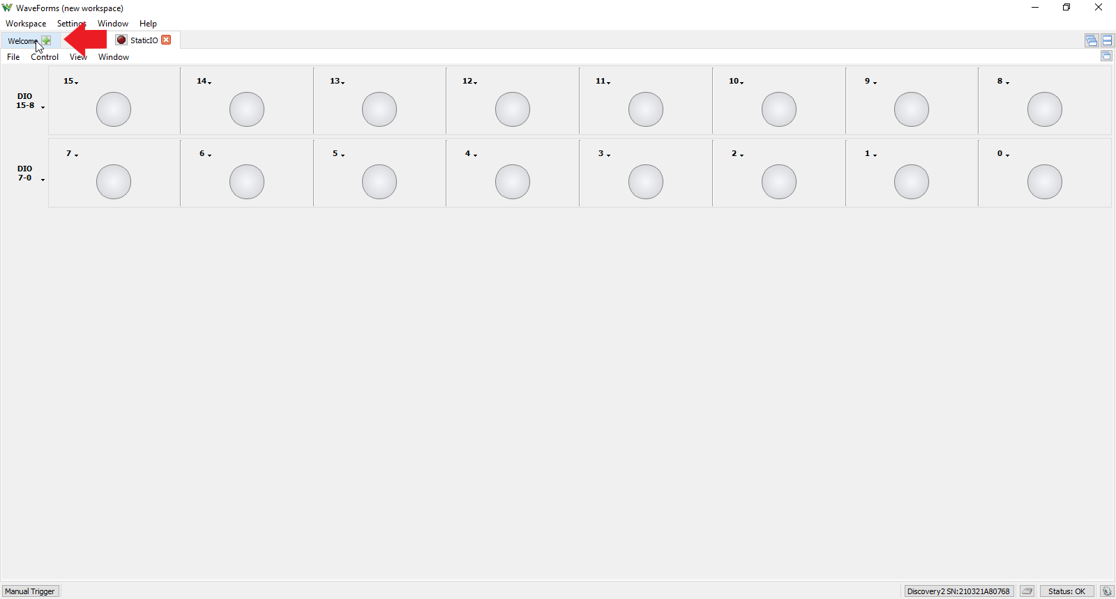
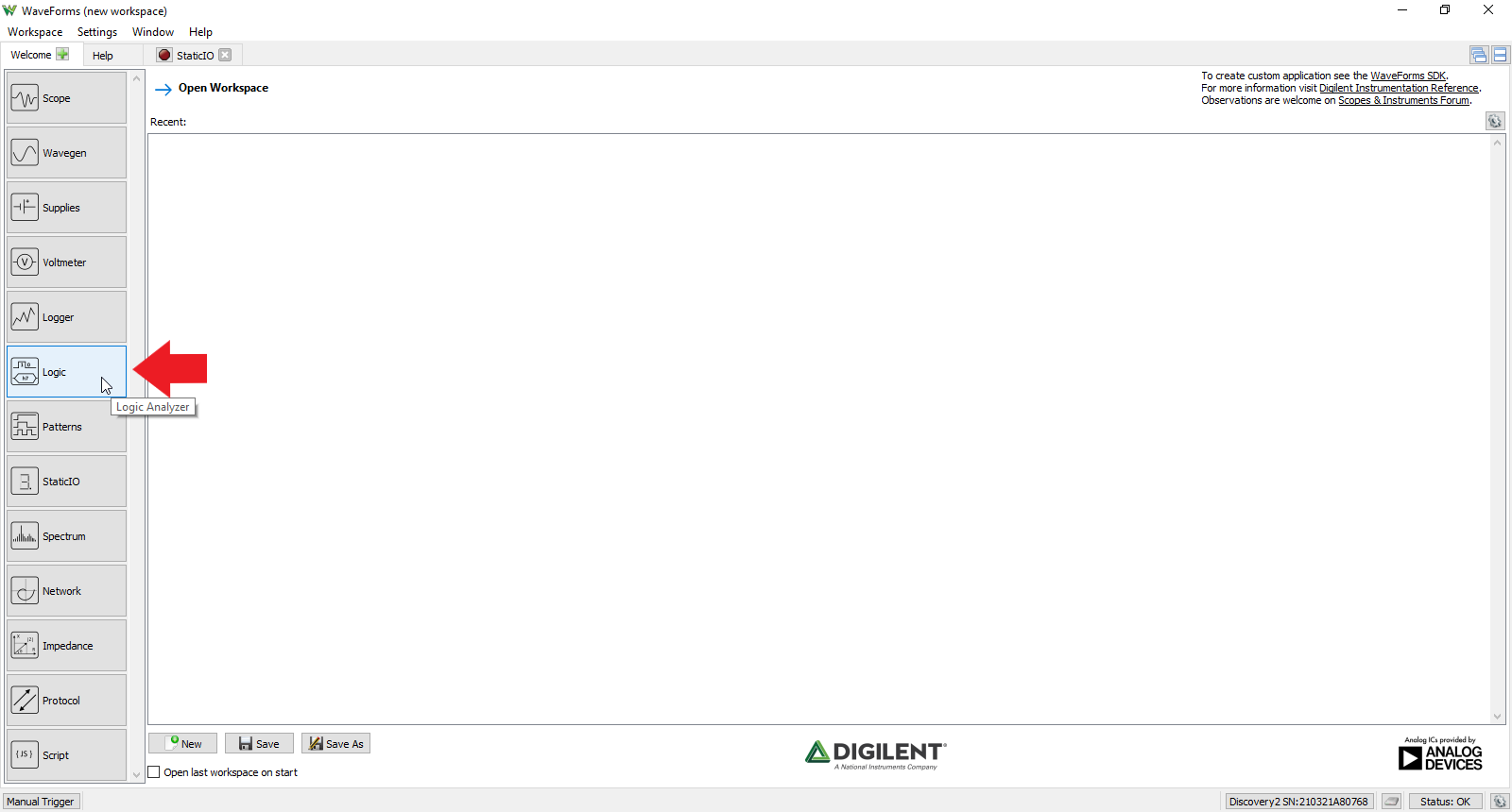
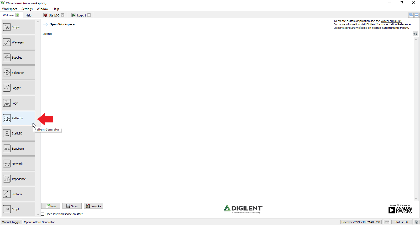
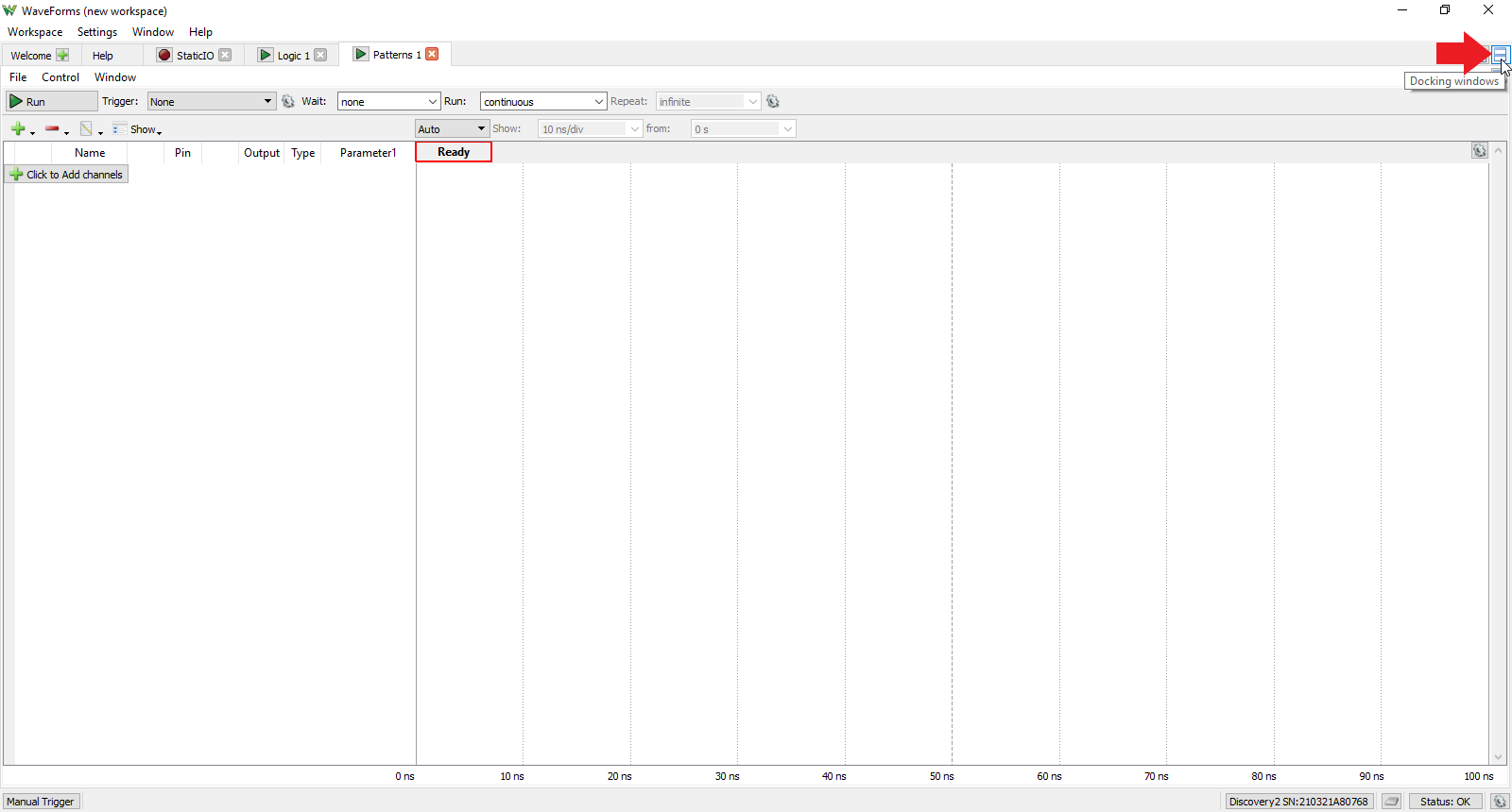
This demo does not require any hardware setup but relies on the Logic Analyzer and Pattern Generator tools in Waveforms. To set up these tools and view them simultaneously, follow these steps.
2.1.6
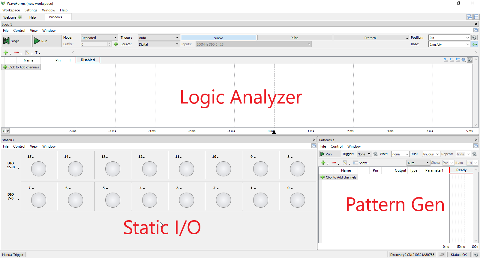
Now, the Static I/O, Logic Analyzer, and Pattern Generator tools should all be open and viewed together in the same window with the Logic Analyzer in the top portion of the window, the Static I/O in the bottom left portion of the window, and the Pattern Generator in the bottom right portion of the window.
2.2 Blink a Virtual LED
2.2.2
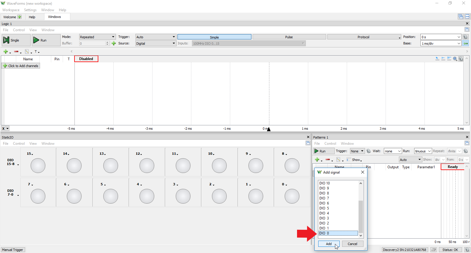
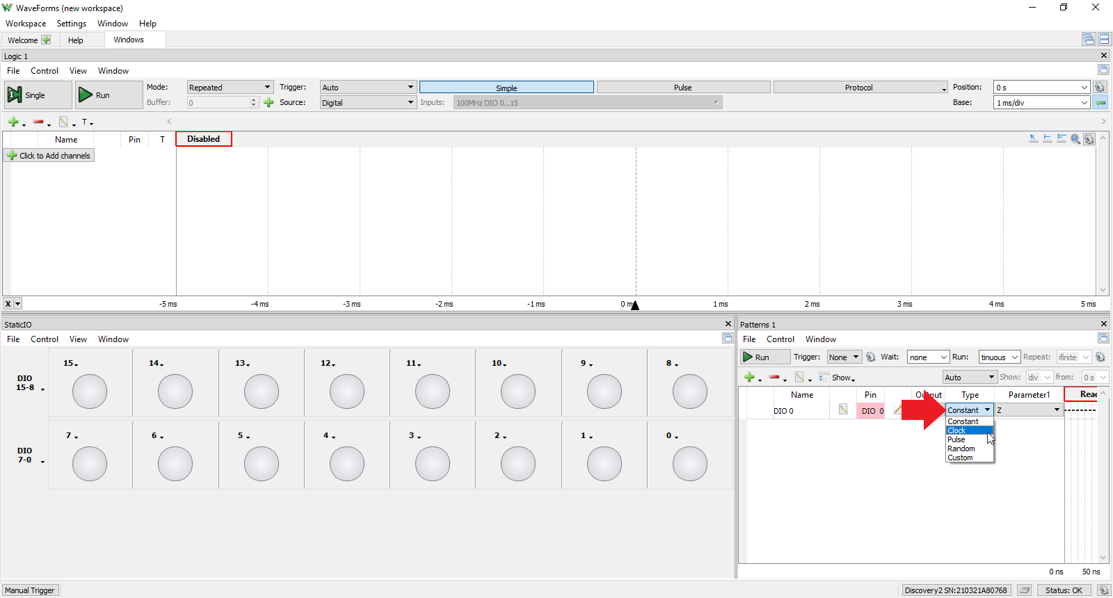
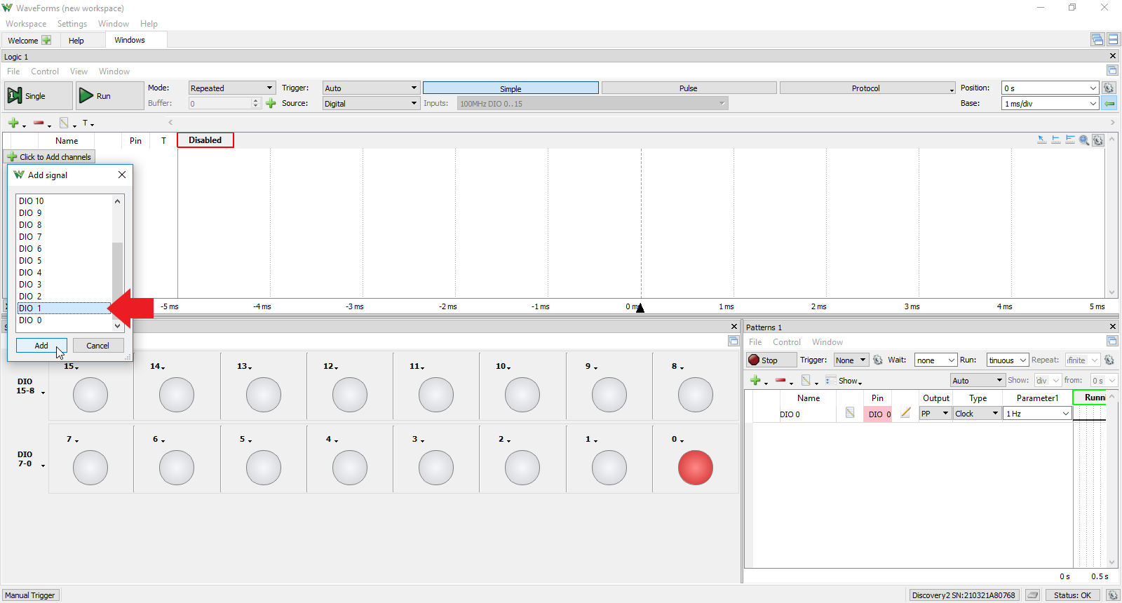
In the “Add Signal” window, scroll down “DIO 0”, select it, and click “Add”. DIO 0 should appear in the Patterns tool window.
2.2.4
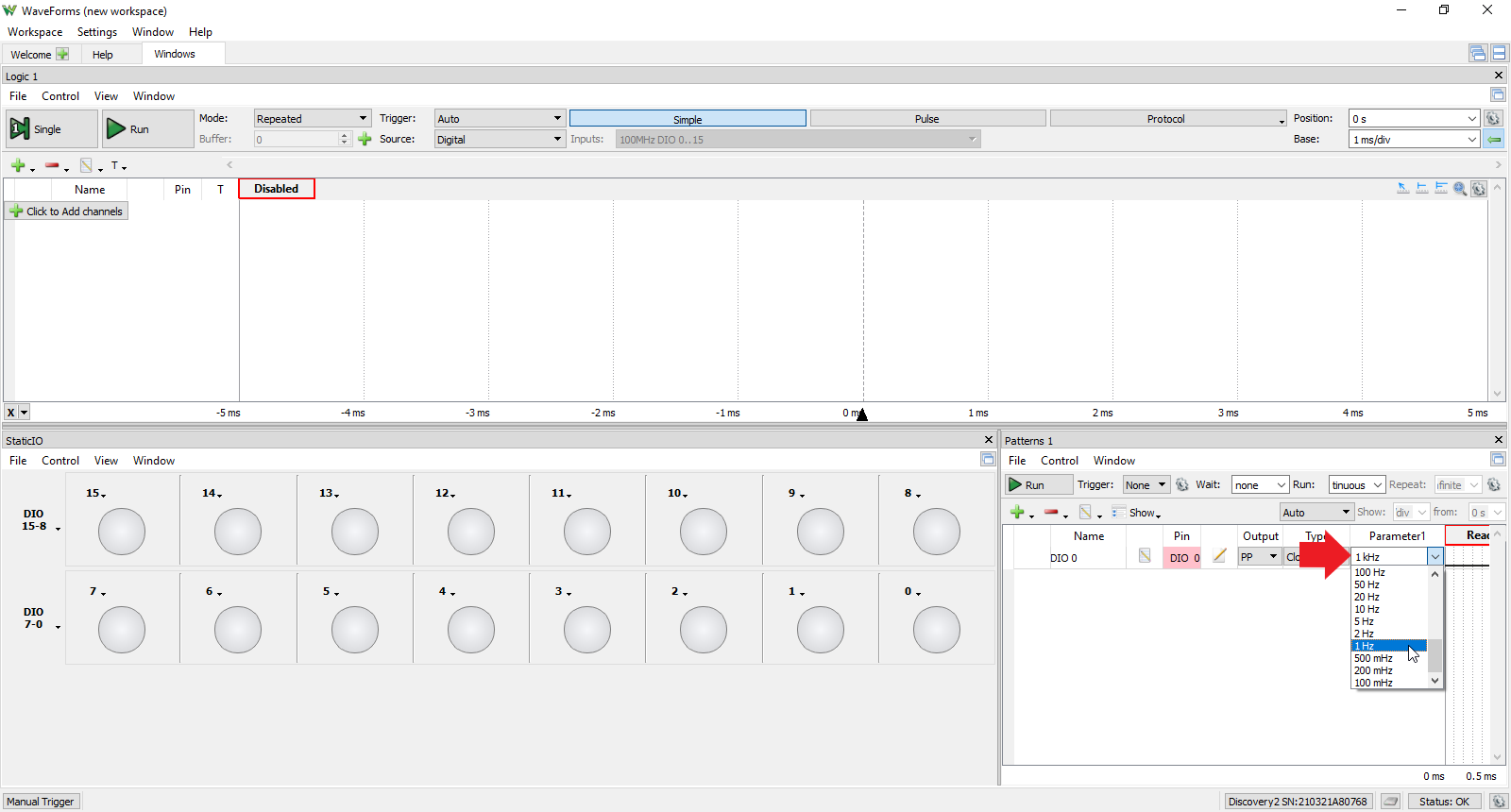
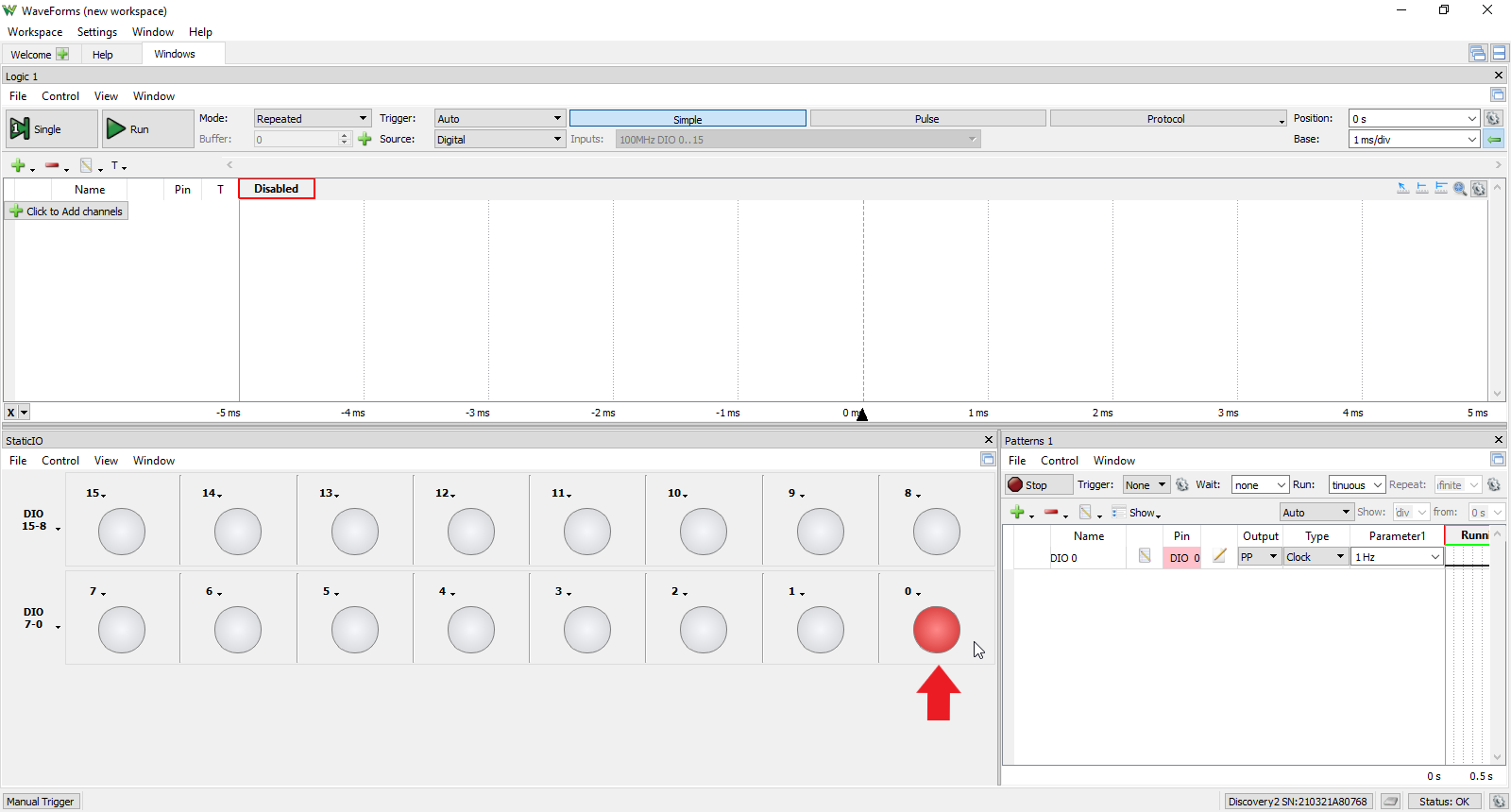
In the Patterns tool window under “Parameter 1”, click the drop down menu, scroll down to and select “1 Hz”.
2.3 Toggle a Virtual Button
2.3.1
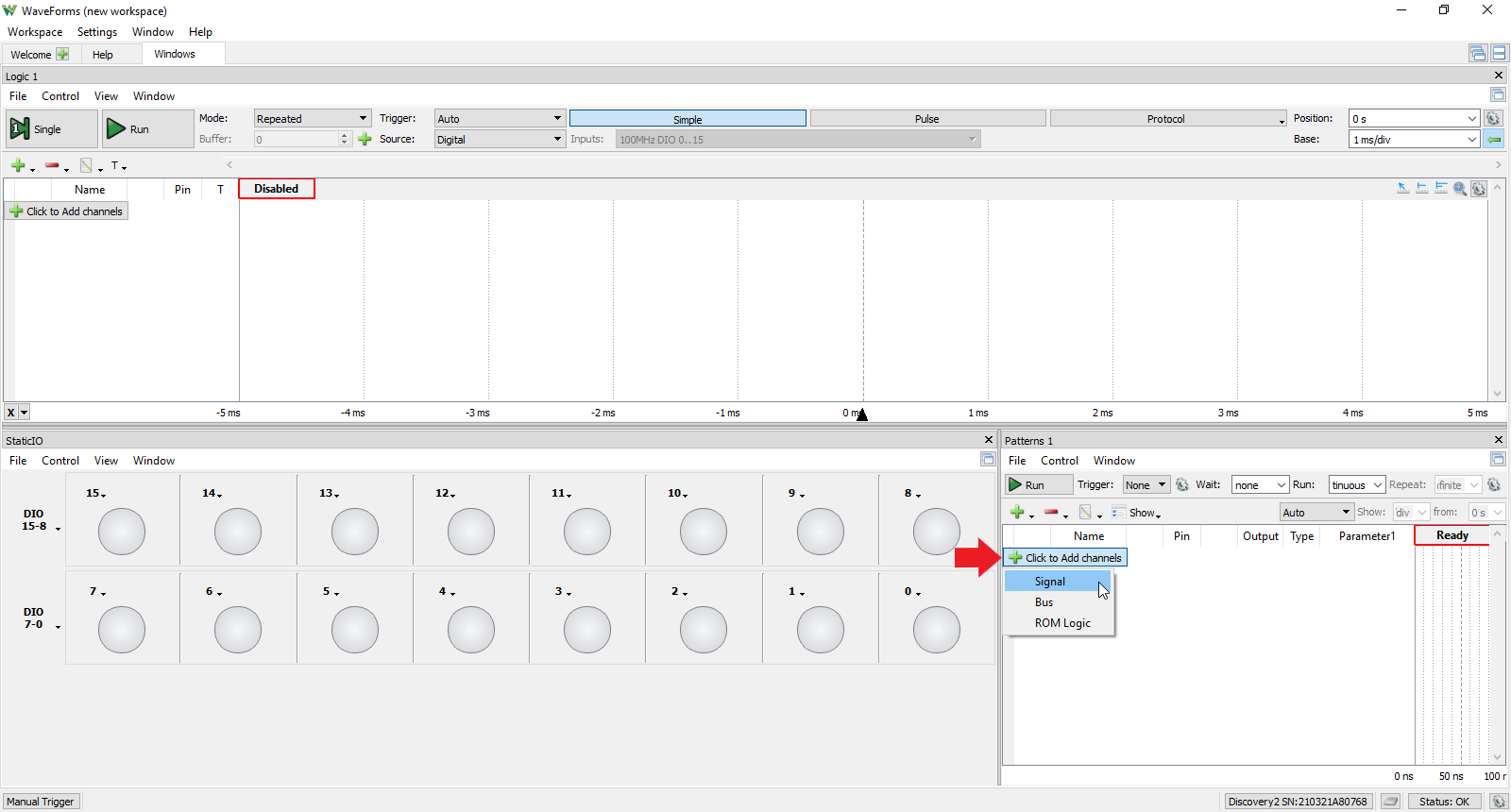
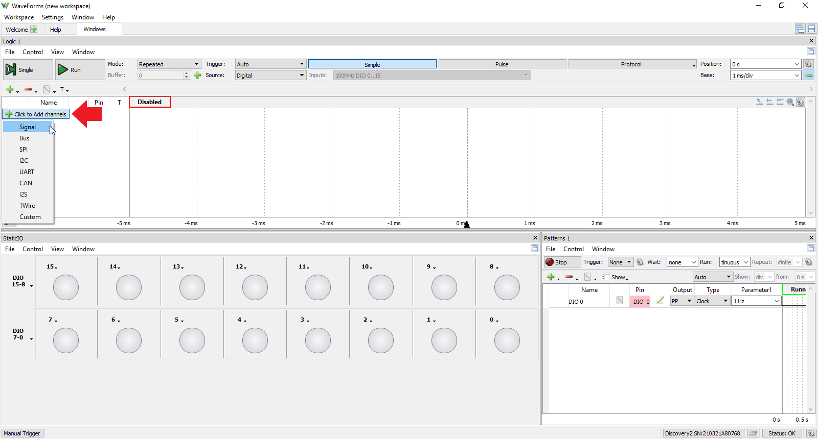
In the Logic tool window, click the “Click to Add channel” button and select “Signal” from the drop down menu.
2.3.3
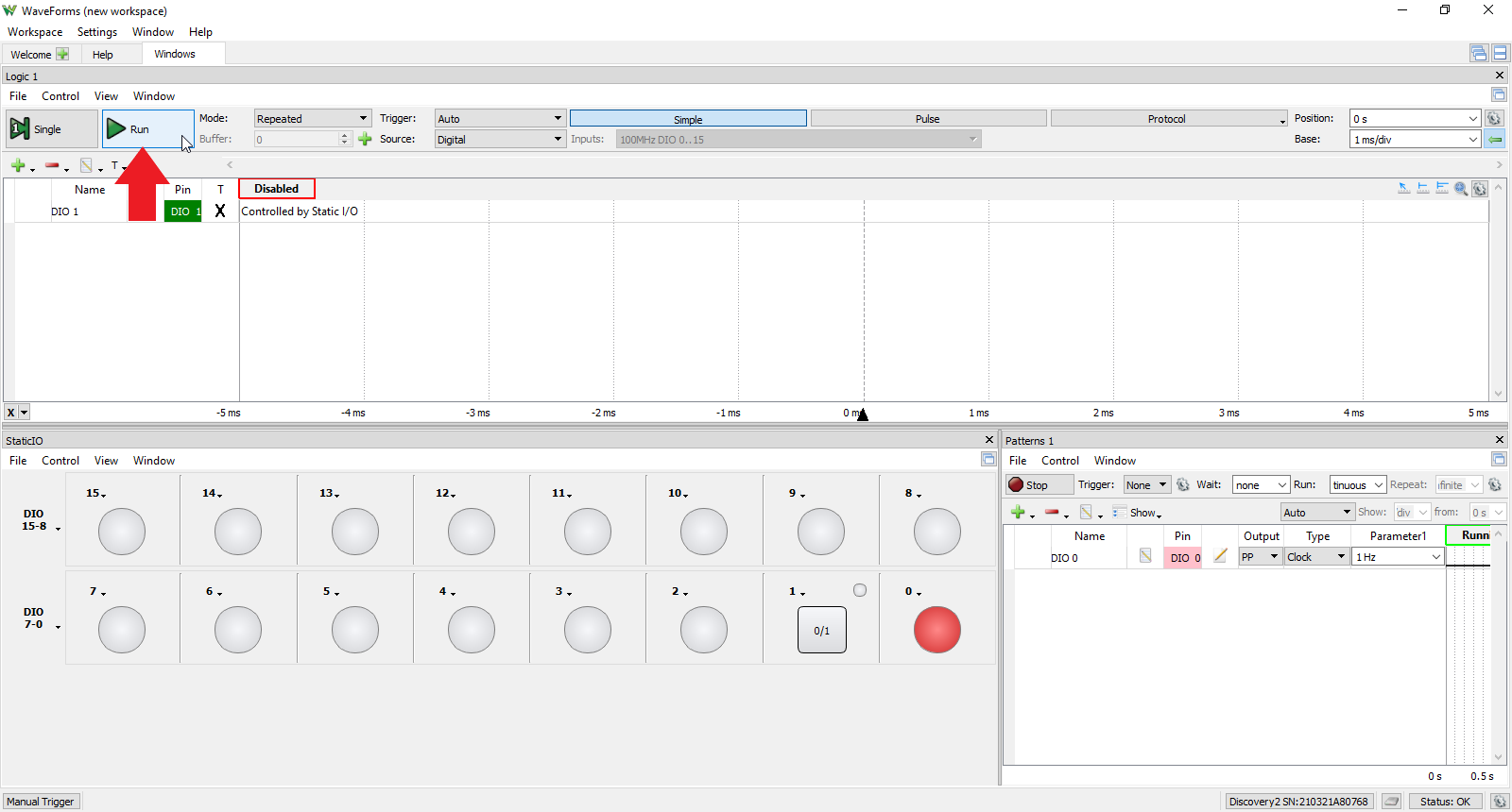
In the Static I/O tool window, navigate to the DIO 1 box next to the flashing DIO 0 box. Click on the downward arrow, select “Button”, and select the configuration at the top of the list (Released: 0, Pressed: 1).
2.3.5
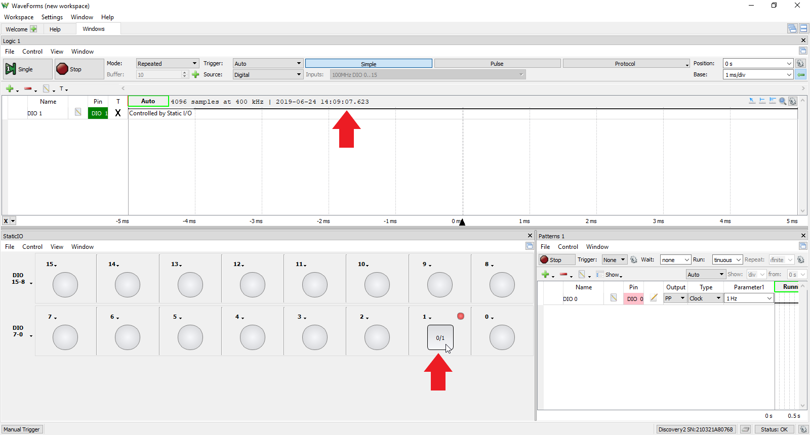
In the Static I/O tool, click on the DIO 1 button and observe the logic level of DIO 1 change from low to high in the Logic tool.
Note: Using Multiple Instruments
The StaticIO instrument can be used with other WaveForms instruments. Using multiple instruments at the same time is helpful in a wide variety of situations. One example would be to use the Protocol Analyzer to configure a device under test, the StaticIO, the Pattern Generator or the Protocol Analyzer to stimulate the device, and capturing the result in the Logic Analyzer, all at the same time. More information on how instruments can be operated together can be found in the Using Cross Triggering guide.
It should be noted that while multiple instruments can use any Digital Input pin, and those pins can be used as Digital Outputs, no more than one instrument can control a Digital Output pin at a time. WaveForms accounts for this by disabling instruments using a shared output, or by displaying a message stating that a shared output is currently used by a different instrument.
3. Static I/O User Interface Overview
This section walks through the various configuration options for the Static I/O instrument. These configurations can be used to interact with and display digital signals and circuits either with the previously explored tools in Waveforms or with external digital circuits. However, the scope of this section will be limited to only configuration with brief application discussions.
3.1 Group Bus Assignments
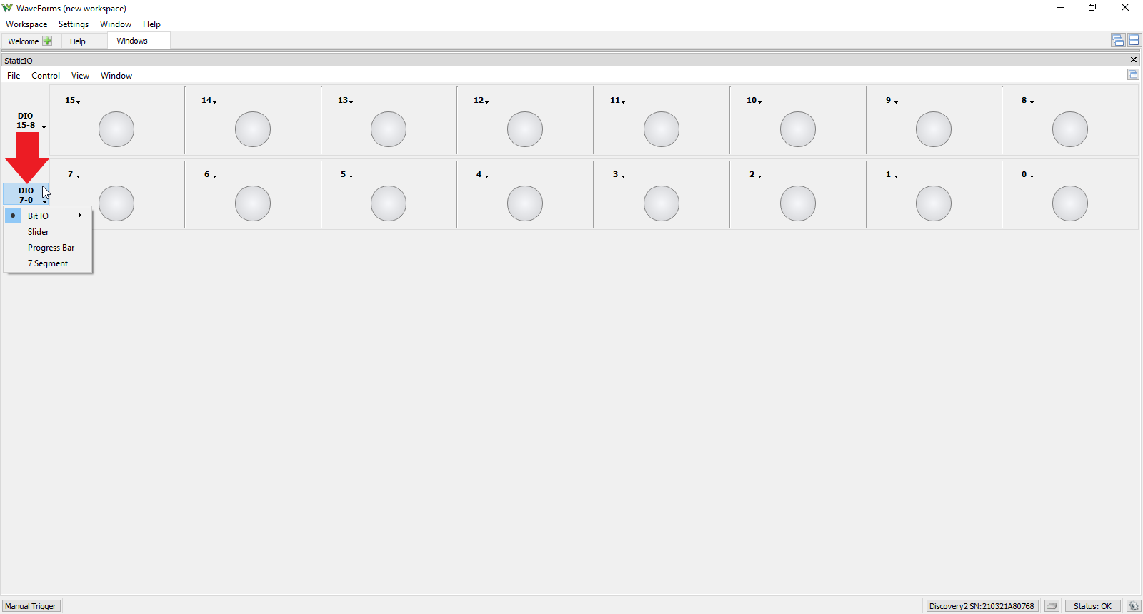
By default, the Static I/O tool opens with all the available DIO lines from your Test and Measurement Device in groups of 8, descending from left to right and top to bottom all configured as LED state indicators for each line. To change a particular group, click on the group configuration drop down menu located on the left of the group row. This menu includes:
- Bit IO: (Input/Output) Last IO, LED, Button, Switch (Discussed further in Section 3.2)
- Slider (Output)
- Progress Bar (Input)
- 7 Segment Display (Input)
3.1.1 Slider
Selecting “Slider” from the group assignments drop down menu groups those eight DIO lines into an 8-bit binary value output that can be changed by either moving the slider left to right or by entering a value between 0 and 255 in the value text field located to the right of the slider bar. The highest digital line is the most significant bit (MSB) and each digital line will get the corresponding bit value related to the bus value.
3.1.2 Progress Bar
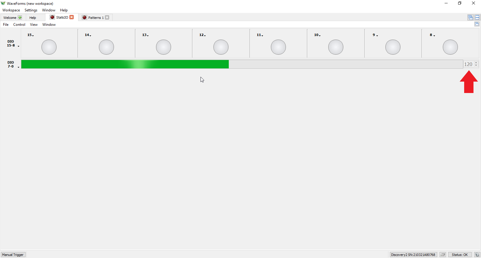
Selecting “Progress Bar” from the group assignments drop down menu groups those eight DIO lines into an 8-bit bus input that displays the binary value of the 8-bit bus as a progress bar (increasing from left to right) and displaying the exact value (from 0 to 255) in the text field to the right of the progress bar. The highest digital line is the most significant bit (MSB) and each digital line will get the corresponding bit value related to the bus value.
3.1.3 Seven Segment Display
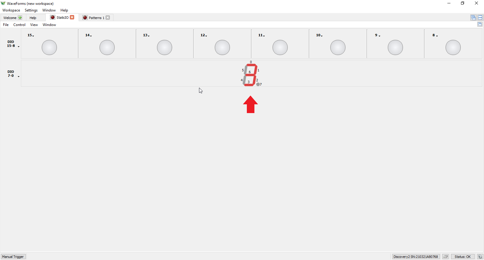
Selecting “7 Segment” from the group assignments drop down menu groups those eight DIO lines into a 7 segment display input. Each of the eight digital lines correspond to one of the segments or the decimal point as seen in the picture to the right. A logic high level illuminates the segment associated with that DIO line.
3.2 Individual DIO Assignments
To change the assignment for an individual DIO rather than an entire group, click on the DIO drop down menu located in the upper left corner of the individual DIO window. This menu includes:
- LED (input)
- Button (input and output)
- Switch (input and output)
3.2.1 LED
The LED input display is the default setting for all DIO lines. This displays the current state of the DIO line: red if logic high, grey if logic low.
3.2.2 Button
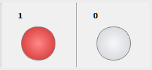
Selecting “Button” from the DIO assignment drop down menu provides six options for how the button performs when pressed or released. Button is both an input and output device with two states (pressed and released) with an LED as a state indicator. 0 corresponds to logic low, 1 corresponds to logic high (LED illuminates), and Z corresponds to high impedance state which will not trigger the LED indicator and will also not drive the DIO line to a logic low or high level which can be useful if multiple devices are connected to the same line. Image A shows the options for the button behavior and image B shows two examples of buttons in the release state and their corresponding LED indication.
3.2.3 Switch
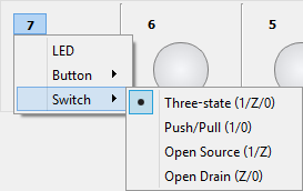
Selecting “Switch” from the DIO assignment drop down menu provides four options for how the switch performs. Switch is an input and output device with the output dependent on the switch state selection. Like the Button device, 0 corresponds to logic low, 1 corresponds to logic high (LED illuminates), and Z corresponds to high impedance state which will not trigger the LED indicator and will also not drive the DIO line to a logic low or high level which can be useful if multiple devices are connected to the same line. Image A shows the four options for the switch's behavior and Image B shows three examples of switches in 0,1,and Z states with their corresponding LED indication.
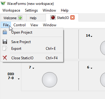
3.3 File Menu
The File drop down menu has four options:
- Open Project: opens a previously saved workspace
- Save Project: saves the current workspace
- Export: exports an image of the current Static I/O tool
- Close StaticIO: closes the Static I/O tool
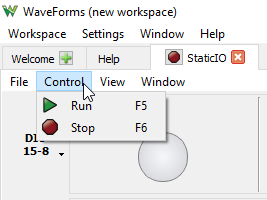
3.4 Control Menu
The Control drop down menu contains two options:
- Run: begins the Static I/O tool operation (also accessible by pressing F5)
- Stop: halts the Static I/O tool operation (also accessible by pressing F6)
3.5 View Menu
The View drop down menu allows the user to toggle on/off custom name text fields for each DIO line, seen at the bottom of the individual DIO line windows as seen in the picture to the right. Type in the text field to change the DIO line's custom name.
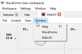
3.6 Window Menu
The Window drop down menu allows selection of:
- Help menu (also accessible by pressing the F1 key)
- Welcome page (Waveforms)
- Any other Waveforms tool that has been opened from the Welcome page.
Next Steps
For more guides on how to use the Digilent Test & Measurement Device, return to the device's Resource Center, linked from the Test and Measurement page of this wiki.
For more information on WaveForms visit the WaveForms Reference Manual.
For technical support, please visit the Test and Measurement section of the Digilent Forums.


